Physical Computing Quick Reference for the PIC (18F452)Physical Computing BookBack To Main Physical Computing Page |
Get the full story in convenient book form: |
Physical Computing Quick Reference for the PIC (18F452)
Physical Computing Book
Back To Main Physical Computing Page
Get the full story in convenient book form:
 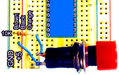 |
' in PicBasic Pro, we need these lines at the top of our program ' to set the pin that we're debugging on, and the baud rate at which ' to send debug messages: INCLUDE "modedefs.bas" DEFINE DEBUG_REG PORTC DEFINE DEBUG_BIT 6 DEFINE DEBUG_BAUD 9600 DEFINE DEBUG_MODE 1 ' declare a variable called X: X var byte ' make pin B0 an input pin: Input portb.0 Main: ' read the value of pin B0 into the variable X: X = portB.0 Debug ["X = ", DEC X, 10, 13] Goto main |
Flashing
Led |  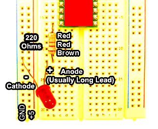 | |
| Relays for turning anything on and off. Used most commonly with AC power. | 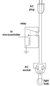 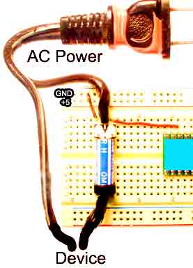 | |
Transistor
Circuit for turning on and off DC devices. | 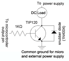 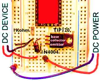 |
' Put pins into input mode: input
portB.0 input portB.1 input portB.2 MyLoop: ' turn off the "switches off" LED:
Low portC.1 'if all the switches are on then turn off the "switches off" LED '
and go to the flash routine: if portb.0 = 1 and portb.1 =1 and portb.2 = 1 then
' Turn on the flashing LED, and turn off the "switches off" LED: High portC.2
Low portc.1 Pause 100 ' flash the flashing LED: Low portC.2 Pause 100 High portC.2
Pause 100 Low portC.2 else ' if any switches is not on, turn on the "Switches
off" LED: High portC.1 ' turn off flashing LED: Low portC.2 endif Goto MyLoop
Standard ADC Input Circuit for use with any variable resistor with two leads | 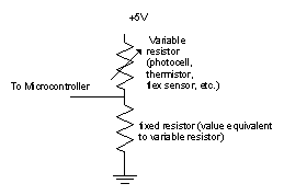 | 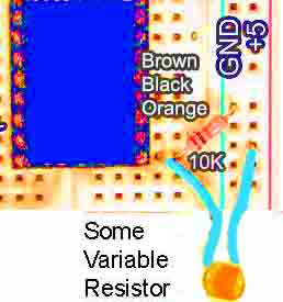 |
| ADC Circtuit for use with a pot. | 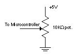 | 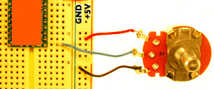 |
'
Set Debug pin port DEFINE DEBUG_REG PORTCB ' Set Debug pin BIT DEFINE DEBUG_BIT
6 ' Set Debug baud rate DEFINE DEBUG_BAUD 9600 ' Set Debug mode: 0 = true, 1 =
inverted DEFINE DEBUG_MODE 1 ' Define ADCIN parameters DEFINE ADC_BITS 10 ' Set
number of bits in result DEFINE ADC_CLOCK 3 ' Set clock source (3=rc) DEFINE ADC_SAMPLEUS
20 ' Set sampling time in uS ' declare a variable to hold the result: ADCVar var
word TRISA = %11111111 ' Set PORTA to all input ADCON1 = %10000010 ' Set PORTA
analog and right justify result Pause 500 ' Wait .5 second main: ' read ADC channel
0: adcin 0, ADCVar ' debug the raw value (the value 13 makes the return): debug
"ADCVar: ", DEC ADCVar, 13, 10 GoTo main
| RC Circuit for use with variable resistors. You would use this if your microcontroller does not have ADC capabilities or you you have run out of ADC pins. | 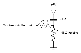 | 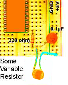 |
'
since RCTime doesn't depend on an ADC, we can use any pin. ' This example uses
pin B0: ' Set Debug pin port DEFINE DEBUG_REG PORTB ' Set Debug pin BIT DEFINE
DEBUG_BIT 6 ' Set Debug baud rate DEFINE DEBUG_BAUD 9600 ' Set Debug mode: 0 =
true, 1 = inverted DEFINE DEBUG_MODE 1 ' set up a variable to hold the result:
RCVar var word Main: ' Take pin 0 high to discharge capacitor: high portB.0 '
hold 1 millisecond to make sure capacitor is discharged pause 1 ' Measure time
it takes to charge again. Rctime portB.0,1,RCVar ' debug the result: debug "RCVar:
", DEC RCVar, 10, 13 goto main
| For Dimming an LED. Doesn't work very well. | 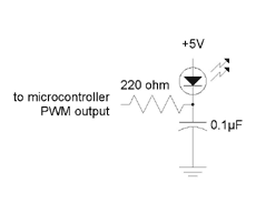 | 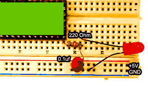 |
'
the LED to be dimmed on pin RC3. period var byte output portc.3 main: for period
= 0 to 255 ' pulse LED (pulsout 1 = 2 microseconds) pulsout portc.3, period '
pause in microseconds; ' pause time gets longer as pulse gets shorter ' pauseus
pauses for microseconds, not milliseconds: pauseus 2*(255 - period) next
goto main
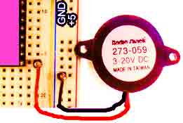
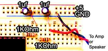
| Tone Generation |
| 
 |
'
declare an array of 12 word variables: pitch var word(12) ' declare other variables:
note var byte ADCVar var word thisNote var word ' the 12 elements of the array
called pitch are the 12 notes of a scale: pitch(0) = 262 ' middle C pitch(1) =
277 ' C# pitch(2) = 294 ' D pitch(3) = 311 ' D# pitch(4) = 330 ' E pitch(5) =
349 ' F pitch(6) = 370 ' F# pitch(7) = 392 ' G pitch(8) = 415 ' G# pitch(9) =
440 ' A pitch(10) = 466 ' A# pitch(11) = 494 ' B main: For note = 0 to 11 ' so
we put the pitch into a normal word variable: thisNote = pitch(note) ' play note:
freqout portc.4, 1000, thisNote, thisNote next goto main
| RC Servo Motor | 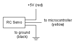 | 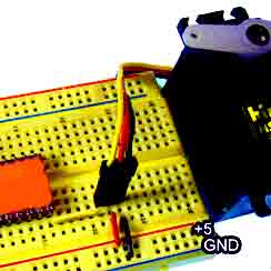 |
'
the servo is on pin C3 ' note: if you use a crystal other than 4MHZ, ' it changes
the pulsewidth of pulsout. ' For a 20MHZ crystal, for example, pulsout is five
times as ' fast, so you'd need to multiply the pulse widths by 5 ' with a 20 Mhz
crystal. DEFINE OSC 4 angleVar VAR word ' set up constants with the minimum and
maximum pulse widths minAngle con 50 maxAngle con 250 ' set up a constant with
the time between pulses: refreshPeriod con 20 ' set an initial pulsewidth: angleVar
= minAngle main: 'take the output pin low so we can pulse it high Low portc.3
' pulse the pin PulsOut portc.3, angleVar ' pause for as long as needed: pause
refreshPeriod ' change the angle for the next time around: if angleVar > maxAngle
Then angleVar = minAngle else angleVar = angleVar + 1 endif GoTo main
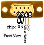 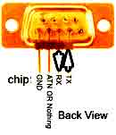 | 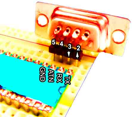 | Programming your chip |
|
| Having your program talk to other computers. |
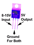
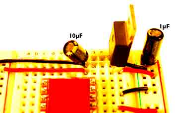
| These are pinouts for a 7508 +5Volt Voltage Regulator. Necessary for the PIC. | Decoupling your power supply by adding these two capacitors will smooth out the flow which is important when you are using things like motors and not a bad idea in general |
 |   |
ASCII Highlights
| Schematic | Pinout Abbreviations+Voltage:Vdd, Vin, Vcc, V+ Transmit: TX Oscillator:OSC Chip Select: CS |
Capacitor
Markings
Resistor Stuff
|
|