by Ching-hsi (Sid) Chou and Tushar Goyal, 2020
Introduction
A building management system, otherwise known as a building automation system, is a computer-based control system that controls and monitors the building’s mechanical and electrical equipment such as ventilation, lighting, power systems, fire systems, and security systems.
Source: https://en.wikipedia.org/wiki/Building_management_system
With the advent of Building Management Systems (BMS), a building is no longer just brick and mortar, it’s now a complex system comprising the technological as well as physical. Figure 1 shows the parts of a typical BMS.

One of the earliest known examples* of building automation is of a school teacher in Milwaukee who came up with a simple idea of letting the operators in the boiler room know when the temperature of the classroom began to drop without either of them having to walk over to the other. He did this by installing a switch in his classroom that controlled a light bulb in the boiler room. When the light turned on, the operators knew to turn the heat up. We’ve come a long way since then in the automation of systems and processes in a building.
*Source:http://www.harcourtbrown.com/a-brief-history-of-building-automation-and-controls/
Open vs Closed Loop Systems
Building management systems enable automation of processes with a reduced degree of any human intervention. The major processes (or subsystems) typically controlled by a BMS are as follows:
- Ventilation
- Temperature
- Power
- Lighting
- Security
- Fire/Emergency
There can be different degrees of automation. Consider how a radiator knob controls the temperature (Figure 2). A radiator works by allowing steam to pass through the radiator pipes which heat the air surrounding the radiator through convection. The knob on the radiator controls how much steam should circulate through the pipes, thereby, regulating the temperature. This is an open loop system, meaning there is no connection between the temperature and the knob which regulates it. The knob has no information about the temperature and hence, when the temperature gets too hot or too cold, a human needs to rotate the knob to change the temperature.

By contrast, thermostats, like the one shown in Figure 3 are closed loop systems that are able to control the heating and cooling mechanisms based on the temperature of a room. They read the temperature of the room and then respond by turning on or off the appropriate cooling/heating equipment required to maintain the temperature at the specified set point.
The main components of a thermostat are:
- Input: a temperature sensor
- Process: The logic function
- Output: The valve to control the cooling/heating
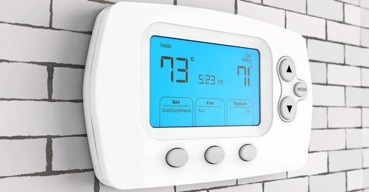
Any ‘intelligent’ system (capable of logic-based decision making) must have an input, a logic function (usually a comparative process) and an output. In the case of the thermostat, the temperature sensor feeds the current temperature value to the logic function which evaluates what needs to be done with the valve. For example, when you set a temperature of 68 degrees and the temperature sensor returns a reading of 66 degrees, the logic function of the thermostat opens the valve and lets more hot air in until the temperature reaches the set point. This process of reading the sensor value, comparing it against the set point and then evaluating the necessary action is something that the thermostat does repeatedly and infinitely.
Automation vs Manual Control
Each of the subsystems in a BMS are closed loop systems, comprised of input sensors, a logic function and output actuators. The input sensors send information to the logic function which decides what the actuators should do based on its evaluation of the sensor data. Sensors might measure things like temperature, the amount of fresh air in the building, number or movement of people in the building, etc. However, all the subsystems may not be fully automated. The occupants of the building may need to have some degree of control over subsystems such as the lighting and the temperature system. Hence, there may be elements of both automation as well as manual control.
For example, the BMS may define a range for the temperature of the building but the occupants have a degree of freedom to control the specific temperature of the various zones within that range. Similarly, the lighting system may be automated based on human movement but the occupants have the ability to override the automated logic and switch the lights on or off. They may also have the ability to control the brightness/tone of the lights. This means the BMS needs to provide for a user interface to interact with these subsystems in addition to their overarching automated logic.
Networking and Protocols
Many subsystems of a BMS rely on information from other subsystems to function correctly. For example, the Dedicated Outside Air System (DOAS) at 370 Jay Street controls the amount of fresh air in the building based on the occupancy of the building among other factors. The higher the occupancy, the more fresh air needs to be let in into the building’s ventilation system. Computer networking is used for relaying information from one source to another as well as to control actuators based on such information. Networking is one of the fundamental building blocks of a BMS, which is why BMSs are often considered Information Technology systems. However, having a large number of sensors and actuators distributed all over a building poses its own challenges from a networking standpoint.
A BMS network can be set up in many ways. A pragmatic approach is a distributed star topology where the sensors on each floor are connected to a central floor hub and each of the floor hubs are connected to the main Command and Control Center (CCC), as shown in Figure 4.
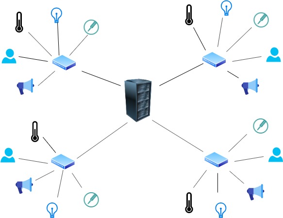
This is also known as the core-periphery network structure. In a BMS, the core typically has a storage attached where it keeps logs of the operational information for the sake of record keeping as well as future analysis. The core may also use the storage for relaying information between different subsystems.
BMS networks are based on the Open Systems Interconnection model (OSI model) just like the internet. The OSI model is a conceptual model that characterizes and standardizes the communication functions of a telecommunication or computing system without regard to its underlying internal structure and technology. Its goal is the interoperability of diverse communication systems with standard communication protocols. The model partitions a communication system into abstract layers. The original version of the model had seven layers, as shown in Table 1.
Source: https://en.wikipedia.org/wiki/OSI_model
| Layer | Function | Example |
|---|---|---|
| Application (7) | Services that are used with end user applications | SMTP |
| Presentation (6) | Formats the data so that it can be viewed by the user. | HTTP, JPG, GIF |
| Session (5) | Establishes beginnings and ends between two hosts | NetBIOS, PPTP, SSH |
| Transport (4) | Responsible for the transport and error handling of packets | TCP/UDP |
| Network (3) | Reads the IP address from the packet. Network addressing (IP addresses) | Routers, IP Protocol |
| Data Link (2) | Reads the MAC address from the data packet. Physical device addressing (MAC addresses) | Switches |
| Physical (1) | Send data on the physical wire or radio signal | Ethernet cable, Hubs, radio |
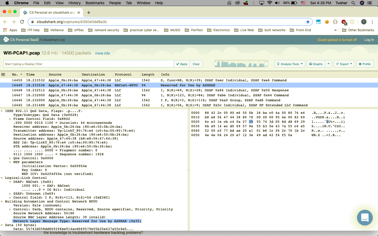
The information from subsystems needs to be made available to other subsystems which means the subsystems need to all talk the same protocol. Enter BACnet. BACnet is a data communication protocol for Building Automation and Control networks, developed under the auspices of the American Society of Heating, Refrigerating and Air-Conditioning Engineers (ASHRAE), specifically for BMS and is used by many large BMS manufacturers like Johnson Controls Inc, Siemens Building Technologies, KMC Controls and Teletrol Systems. The BACnet protocol layers include physical layer, link layer, network layer, application layer and BACnet security layer.
Source: https://www.rfwireless-world.com/Tutorials/BACnet-protocol-stack.html
Source: http://www.bacnet.org/Bibliography/EC-9-97/EC-9-97.html
Physical Wiring
Installing a BMS requires a lot of wiring and ductwork which needs to be planned beforehand. Not only do the wires and ducts need to be laid, but one also needs to adequately provide for additional capacity for future needs of the building. The different kinds of wires that need to be laid for a BMS are:
- Power cables
- Signal (information) / Ethernet / Power Over Ethernet (POE) cables
- Plumbing and ventilation ducts
Further, the information between different clients, servers and the sensors/actuators need to travel over long distances because buildings can be large enough to cover a few blocks and can have many floors.
Information is passed from point A to point B in the form of electrical pulses which send large combinations of 0s and 1s. This such information from one sensor from a floor hub on the 10th floor to the main server in the basement can lead to significant signal degradation which means loss of information. To overcome this, engineers use a protocol such as RS485 which creates a signal-balanced information bus and can be used to carry electrical signals over long distances without considerable degradation. Pairs of twisted wire carry each signal, and the data voltages are inverted on each wire of the pair. That way, the receiver can confirm if there’s a physical transmission error. If the voltages on the two wires of a pair do not add up to zero volts, there’s an error. The information bus can communicate with up to 32 nodes so is ideal for sending information to multiple nodes simultaneously.

The Subsystems
The major subsystems of a typical BMS are as follows:
- Ventilation
- Temperature
- Power
- Lighting
- Security
- Fire/Emergency
The sensors and actuators for each subsystem are provided in Table 2 to provide a high level understanding of these subsystems.
| Subsystem | Input: Sensor(s) | Output: Actuator(s) |
| Ventilation / DOAS | Occupancy sensor | Pump/valve |
| Temperature / HVAC | Temperature sensor, thermostat interfaces | Pump/valve |
| Power | Metering (gas, electric, cooling/heating) | Pump/valve,High voltage relays |
| Lighting | Occupancy sensor, manual switches | Lights |
| Security | CCTV, RFID card sensor | Doors/turnstyles |
| Fire / Emergency | Smoke Alarm | All of the above |
As described above, the fire and emergency systems are different from the rest as they need to be integrated into the BMS in a way such that in the event they get triggered, they not only need to engage the alarm system and the fire hydrant system, but also they need to be able to override and take control of all the other subsystems such as the lighting and ventilation system.
Emergency Systems
Besides automated and manual control, BMS also have Emergency systems that have the ability to override all other systems. In most countries, governmental regulations require that every building have some form of emergency/fire alarm systems. Fire alarm components, i.e. smoke alarms, are installed based on National Fire Alarm and Signaling Code (NFPA 72) in the United States.
In the event of an emergency, the BMS will override the settings of various building systems with the emergency setting. This includes engaging the alarm / fire hydrant systems and also shutting down the heating, ventilation, and air conditioning (HVAC) to prevent smoke from spreading, and turning on the lights/emergency lights to ensure exit routes are visible. During emergencies, occupant inputs are ignored and the emergency settings override both manual and automated settings for safety purposes.
Source:https://bms-system.com/understand-the-basics-of-fire-alarm-system/
Heating, Ventilation, and Air Conditioning (HVAC)
HVAC systems ensure thermal comfort and indoor air quality and regulate a building’s indoor temperature and humidity with air from outdoors. Most BMSes use passive ventilation with their HVAC systems, however, some larger buildings have a dedicated ventilation system that works together with the HVAC system to provide both heating/cooling as well as the desired air quality index. ASHRAE) came up with a standard for indoor air quality which is followed by many such BMS with dedicated ventilation systems.
Heating systems generate heat and provide warmth in HVAC systems. Usually through a boiler, furnace, heat pump, or coil to provide heated water, steam, or air to deliver to each room. On the other hand, air conditioning provides cooling, and often humidity control to the buildings, typically using a refrigeration cycle like heat pumps, or through other conduction media such as water, air, ice, and chemicals are referred to as refrigerants, as shown in Figure 7. Heat can be both transferred or removed by convection, conduction, or radiation.

The building is divided into smaller HVAC zones, which control is based on ASHRAE standard and BMS automatic settings. These zones are created depending on room division, thermodynamics, and fluid mechanics, which means larger rooms can have multiple zones to achieve efficient control. Each zone is paired with a thermostat to provide occupant-control, occupants can adjust the temperature setting of the zone as desired, within a given range. This range limit is set to protect the user and the equipment.
During emergencies, some parts of the HVAC are turned off to prevent smoke from spreading to other parts of the building, oxygen draw to agitate the fire, and prevent the fire from spreading, while other parts stay on to clear fire for visibility to the exit.
Source:https://en.wikipedia.org/wiki/Heating,_ventilation,_and_air_conditioning
Source:https://www.generalac.com/what-are-the-different-types-of-hvac-units/
Dedicated Outside Air Systems (DOAS)
Ventilation (the V in HVAC) is the process of replacing indoor air with outside air to help the removal of moisture, odors, smoke, heat, dust, airborne bacteria, carbon dioxide, and other gases. In some BMS, it is managed by a Dedicated Outdoor Air System, or DOAS.
A DOAS is a type of HVAC system that consists of two parallel systems: a dedicated system for delivering outdoor air ventilation and a paralleled system for handling the loads generated by indoor and those that pass through the building enclosure. A Dedicated Outside Air System provides dedicated ventilation rather than ventilation as an incidental part of the process of conditioning interior air, as shown in Figure 8. Fresh air is brought in through intake units on the building’s roof. Within the DOAS, air is blown across dessicant wheels, like those shown in Figure 9, to manage the humidity within the building regardless of the outdoor humidity levels.
Sources: https://en.wikipedia.org/wiki/Dedicated_outdoor_air_system

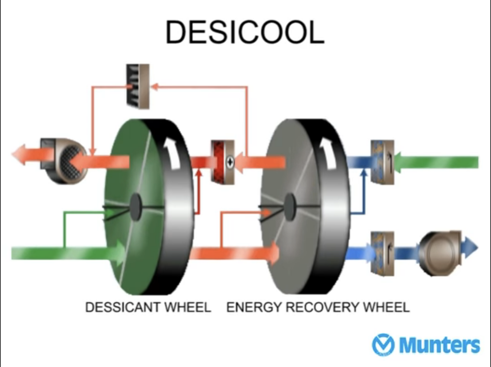
Source: DesiCool explanation video, Cleanfax.com How Dessicant Dehumidifiers Work (part I)
Financial Viability
Electricity is the second highest operating expense of any business after rent. Needless to say, 30-50% savings in electricity can have a huge positive impact on a business’s profits. This is why Building Automation Systems, even though not cheap, can justify the huge financial investment over a span of just a few years.
Let’s consider an example:
Say, the electricity cost of 370 Jay Street is $1.2mm and the cost of the BMS is $1mm (these are arbitrary figures, not based in actual data). If a BMS can provide a saving of, say, a third of the electricity expense i.e. $0.4mm then the BMS would cover its initial investment in 2.5 years ($1mm / $0.4mm) and also provide regular cost savings (or increased profit) to the tune of $0.4mm annually for the future years.
Conclusion
BMS provide many benefits besides reduction of operating cost through energy optimization, such as:
- better monitoring of resources/equipment,
- early detection of system failures,
- tracking of performance degradations,
- logging of data for trend (future) / fault (past) analysis,
- increased safety due to emergency systems
Thus, Building Management Systems are increasingly becoming an important technological investment to real estate, particularly for large commercial/residential buildings or factories where future savings from the BMS can justify its initial financial outlay.
Authors:
Ching-hsi (Sid) Chou – www.sidchou.com
Tushar Goyal – www.tushargoyal.xyz