What is fiber?
If you’ve seen a Verizon Fios commercial or heard Google Fiber is coming to your town, you may have heard of fiber and have some sense that it has to do with faster internet. Over the past several decades, the world’s communications networks have been increasingly replaced with fiber optic connections. But what is fiber, how does it work, and why is it’s use expanding so much?

Conventional fiber optic filaments or simply “fiber,” are thin strands of glass or plastic (the core) surrounded by another material with lower refractive index (the cladding), usually another type of glass or plastic. The refractive index is a number (the ratio of the speed of light in a vacuum to the speed of light in a material) that represents how much light is bent, or refracted, when light enters the material. A vacuum has a refractive index of 1 while all materials have a refractive index greater than 1 (light always travels slower through a material than in a vacuum) and less than 4.
A “primary buffer coating” protects the interior layers from external elements that might damage them. For most applications, ultra-pure glass is used for both the core and cladding resulting in strands about the diameter of a human hair. This structure allows light to travel from one end to the other by reflecting against the core-cladding boundary down the length of the filament.
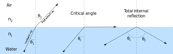
Total internal reflection is the principle that characterizes this propagation of light. The transmission is very fast: about two-thirds the speed of light.
299,792,458 m/s (speed of light) x 2/3 = 199,861,639 m/s
The illustration above shows the principle of total internal reflection. Air has a refractive index of about 1.0027 (n2) and water has a refractive index of 1.333 (n1). This means that light travels 1.333 times slower in water than in a vacuum. Because air has a lower refractive index than water, light travels faster in air than in water. Total internal reflection works whenever a ray of light travels through a medium and hits the boundary of another medium with a lower refractive index at one of several angles that allow the light to be reflected back.


Fiber optic cable refers to one or more fiber filaments encased in a protective jacket. Depending on where the cable will ultimately be installed, different types of insulation, a strength member, or tubing may be used to encase the cable. Fiber optic cables have many applications across industries. Timbercon, a fiber optic manufacturer, includes information on several industries that rely on fiber on their website:
- Illumination, image transfer, and laser signal delivery for medical devices
- Defense applications including for SONAR and aircraft wiring
- Telephone systems
- Cable Television and High Definition Television
- Networking between computers in a variety of settings, including the Internet
History & adoption in telecommunications and networking infrastructure
In the early 1800’s, Swiss scientist Jean-Daniel Colladon did the first experiments demonstrating light could travel through water, creating “light pipes,” using the principle of total internal reflection. This set the stage for over a century of experimentation that led to fiber optics being used in long-distance communication and data transfer. In the early 20th century, fiber optics were primarily used in medicine, to see inside the body. In the 1960’s, Charles Kao discovered that by using pure glass that was free of impurities, light could travel far enough as to be useful for long-distance information transfer. Glass with impurities dims, or attenuates, light. Attenuation is the rate at which flux (like light, or sound) decreases intensity through different media. Attenuation depends on the wavelength and energy as well as the materials it’s passing through. Glass with impurities, like plastic fiber, have higher optical attenuation (a higher attenuation coefficient) than more pure glass, which meant fiber before Kao’s discovery had a short range. He won the 2009 Nobel Prize in Physics for this contribution.
,1884.JPG)
In the 1970s and 1980s, researchers at the American company Corning Glass Works made additional improvements that lowered the attenuation of glass fiber further. Then, by speeding up the manufacturing of high-quality glass fiber, they were able to become competitive with copper wire on cost. Fiber conferred many other important advantages as well:
- Higher bandwidth means they can carry more information
- Fiber optic cables can transmit data over longer distances without needing a repeater, an amplifier that repeats the signal
- With optical transmission, there are no electromagnetic interference problems, and cables do not radiate energy
- Cables are smaller and lighter
- They require less energy to send transmit signal and thus also generate less heat
- They typically have a longer lifespan
- All of these advantages together mean fiber optic networks can be more reliable and consume less power
The first fiber-optic telephone system was deployed by General Telephone and Electronics in Long Beach, California in 1977. The system ran at 6Mbps and could carry the equivalent of 672 voice channels, or individual phone connections (an uncompressed phone call requires 64 kbps, while compression can lower this to 32 or even 16 kpbs). TAT-8 was the 8th trans-Atlantic communications cable but the first fiber-optic one, and came into use in 1988. In the decades since, fiber has become increasingly ubiquitous: Arstechnica reported in 2010 that 99 percent of the physical distance of the world’s internet has been strung with fiber. And Moore’s law applies to fiber optic transmission equipment as well: about every 18 months, capacity at the same price doubles.
Companies are increasingly providing fiber connections closer to customers, allowing for faster broadband speeds. These so called “last-mile” connections are the most economically difficult to implement and justify.
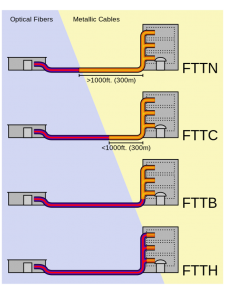
- FTTC/FTTN (Fiber to the Curb or Node) is fiber that’s laid to a nearby node but then copper wires complete the connection inside the building. This is the most common and widespread connection, since companies can serve large numbers of end customers that connect to the nearest node. It will not provide broadband speeds as fast as connections that bring fiber even closer to a customer.
- FTTB (Fiber to the Building/Business/Block) connections run fiber all the way to the building or block of an end user. This allows a faster connection than FTTC/FTTN.
- FTTP/FTTH (Fiber to the Premises/Home): Fiber that’s laid from an ISP to an end user’s home or building. This provides the fastest connection, though it is the most difficult to install and not yet available in most areas.
Sending light & information through fiber optic networks
Light can take several paths as it bounces down the optical core. Each of these paths is called a mode. A mode can have waves of different frequencies as long as they are distributed in space the same way, resulting in a single beam of light. A zero order mode would be a perfect, direct path down the core. The highest order mode is the longest path, and the lowest order mode is the “realistic shortest path,” since zero order is so unlikely.

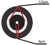
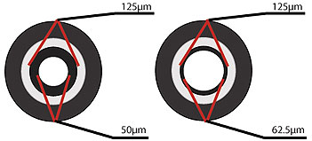
Fiber optic filaments are manufactured with varying core to cladding ratios. The aspect ratio is the core diameter divided by the cladding diameter. The aperture, or light acceptance refers to the area of the core which will accept light. A single mode fiber optic cable has a small diametrical core that allows for one mode of light to propagate. Multimode fiber optic cable has a large diametrical core that allows multiple modes of light to propagate.
Multimode fibers have a larger core diameter (0.05–1.0 mm) than single mode fibers, which results in a higher-order pattern as light propagates. A very small core diameter (between 0.002 and 0.01 mm) allows light to travel at its lowest-order mode, making propagation very efficient.
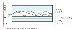
Modal dispersion is when some light travels a longer path down the fiber than others, and the pulse of light spreads over time. Multimode fibers tend to have higher modal dispersions, and so are used over shorter distances. Single mode fiber has higher bandwidth (up to 100,000 GHz) than multimode cable (more like 1GHz) and so is generally favored for long-distance and undersea cables.
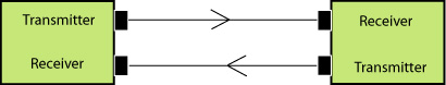
In order to build a communication system with fiber optics, a transmitter to produce and encode light signals and optical receiver to receive and decode those signals are also necessary. A transmitter is physically close to the fiber and uses LEDs (usually used with multimodal cable) or lasers (usually used with single mode cable) to send light. It may even have a lens to focus the light into the fiber. The light is modulated (a digital signal would be “on” and “off” in sequence) and the receiver on the other end uses a photocell or photodiode to detect the light. The receiver decodes the signal into an electrical signal that can be transported by an older medium or understood by a device.
A fiber optic data link consists of the receivers and transmitters that connect the inputs and outputs of the system. A typical data link transmits over two fiber optic cables: one for transmitting and one for receiving.
A transceiver is a device that both transmits and receives signals.
Some links might also use Wave Division Multiplexing (WDM), where multiple wavelengths of light are sent down one fiber by combining them (multiplexing) and later separating them (de-multiplexing). This allows for multiple communication streams to be sent with a single light pulse, or bi-directional transmission over a single fiber. Transponders are transmitters and responders, and are functionally similar to transceivers. While transceivers are limited to electrical-optical function, transponders can also convert optical signal at one wavelength to optical signal at another wavelength, making them ideal for WDM systems.

Even with the many advances in attenuation, there is still loss of light. This can be caused by material absorption or scattering, both issues related to light colliding with atomic structures in the core. Bending can cause loss if the fiber is bent too tightly, or crushed. Microscopic defects or damage to the core can also cause loss. Attenuation is measured in decibels per kilometer. The attenuation coefficient of a cable is important in calculating loss and determining whether a signal will arrive at the receiving end of the link with enough input power to meet the requirements of the receiver.
Optical regenerators, or repeaters, may be necessary to boost the light signal over long distances (over 1km for multimodal and up to 50-80 km for single mode). To repeat the signal, small amounts of special elements are added to the fiber, in a process called doping. These special molecules are excited by specific wavelengths of light energy and then emit a new, stronger light with the same characteristics as the incoming light. Erbium is often used as a doping element because it is excited by the wavelengths most commonly used in long distance fiber links.
Manufacture, installation, & maintenance
Glass fiber is made through a process of modified chemical deposition, a common manufacturing technique that results in a very pure glass core. The fiber is then tested and categorized for different uses. Depending on the harshness of the environment where it will be installed, different types of casings will be applied. For example, submarine cables require a lot of protection as they approach the shore, as the hazards from human and shark activity become greater.
Fiber optic terminations or joints are made either permanently by splicing or by using a connector. The more common splicing method is fusion splicing: fiber is stripped, cleaned, polished, and cleaved so that the fibers to be fused together are almost perfectly aligned. It is inspected with a microscope and heat is applied. The goal is to have a result unrecognizable from unspliced fiber, but there is often some amount of loss. As fiber has become more ubiquitous, the variety of connectors available has increased. These often work like plugs, with different designs and casings suited for different environments.

Dark fiber is fiber that has been installed but is not being used. Around the early 2000s the consolidation of major communications companies led to underuse of some fiber, which was ultimately leased by governments, banks, or other private enterprise. It is considered lit fiber once information starts flowing through it.
Risks
I asked Hunter Newby, self-proclaimed “landlord of the internet” whether global warming was posing a threat to fiber optic landing sites for undersea cables, which are often on the coast. He pointed out that often these areas are already at risk of natural disasters: hurricanes, tsunamis, and earthquakes all pose substantial risk to these sites and do sometimes cause disruptions in service, sometimes slowing traffic to large geographic areas for long periods of time. Perverse funding incentives also mean cables are built in risk-prone locations for short-term economic return. Further, global warming might actually open up new areas to fiber, such as with the Arctic Fibre Project.
Cables also face risks from international terrorism and vandalism. The location of cables is known, and many are not well secured or monitored.
The information running through fiber optic cables is also not necessarily secure. The Wall Street Journal reported in 2001 that former Intelligence officials confirmed they successfully tapped and undersea fiber optic cable in the mid-1990s with a customized spy submarine. According to the their sources, the NSA realized it would be much more technologically and physically complicated to tap fiber optics cables than it had been to intercept telephone or radio communications. Since then, it has been reported that the U.K. and U.S. governments have both tapped undersea fiber optic cables and in theory there are a number of methods by which to do so. While the legality of domestic taps can be questioned, functionally, people have noted that traffic could easily be rerouted in order to be categorized as international data capture, which is not subject to the same oversight and scrutiny.
References
- General
- Fiber Optics article from the Encyclopedia of Computer Science
- Fiber optics kit assembly manual
- FOA Guide to Fiber Optics & Premises Cabling
- What is it/what’s it made of:
- Explanation of fiber core from wikipedia
- Explanation of fiber cladding from wikipedia
- Cisco Press’ Fiber Optics Technologies Articles by Vivek Alwayn, Chapter 3
- What is a fiber optic cable? From Lifewire
- Juniper networks’ explanation of power budgets calculations
- Overview of fiber optics from Explain That Stuff
- History/adoption: How long has it been around? Who invented it? What are its applications?
- Fiber optic communication technology wikipedia page
- Important People & breakthroughs summarized by Timbercon
- Cabling cost comparison (2000)
- Explanation of FTTP/FTTB/FTTN
- How does light travel through fiber?
- Refractive Index wikipedia page
- Timbercon fiber optics presentation
- How stuff works: fiber optics
- How does data travel? Transmitted and received? What does it mean to splice a cable and why do you do it? What does the juncture to “the last mile” look like?
- Fusion splicing wikipedia page
- Blog post explaining transponders
- What’s the difference between transceivers and transponders?
- FOA Guide explanation of a data link
- FOA Guide explanation of amplifiers
- FOA Guide explanation of fiber optic terminations and junctures
- What is lit fiber and what is dark fiber?
- Ingrid Burrington’s Networks of New York
- What is the relationship between fiber optic cable and power networks?
- The manufacturing process
- How products are made: fiber optics
- Politics/Space
- Warning: Do Not Dig: Negotiating the Visibility of Critical Infrastructures, Nicole Starosielski (2012)
- Beaches, Fields, and other Networked Environments, Nicole Starosielski
- Arctic Fibre Project, Amy Nordrum, IEEE Spectrum (2014)
- Why Undersea Internet Cables are More Vulnerable than You Think, Alexandra Chang, Wired (2013)
- String of West Coast attacks on Internet fiber optic cables leads to FBI investigation, Will Greenberg, The Washington Post (2015)
- Spying
- Deep Secrets: As Technology Evolves, Spy Agency Struggles To Preserve Its Hearing — Its Limited Success in Tapping Undersea Cable Illustrates Challenges Facing NSA — Huge Haystack, Few Needles, Neil King Jr., Wall Street Journal (2001)
- Cryptome response to Wall Street Journal article
- The Creepy, Long-Standing Practice of Undersea Cable Tapping, Olga Khazan, The Atlantic (2013)