In this lab, you’ll send data using asynchronous serial communication from a single sensor to a Processing sketch on a personal computer that will then graph the sensor’s value onscreen.
Introduction
Asynchronous serial communication, which you’ll see demonstrated in this lab, is one of the most common means of communication between a microcontroller and another computer. You’ll use it in nearly every project, for debugging purposes if nothing else.
The Processing sketch in this exercise graphs the incoming bytes. Graphing a sensor’s value like this is a useful way to get a sense of its behavior.
These videos will help to understand this lab:
- Video: Introduction to Serial Communication
- Video: Serial Under the Hood: Interpreting Serial Data
- Video: Reading Serial Input in Arduino
- Video: Serial From Arduino to Processing
What You’ll Need to Know
To get the most out of this Lab, you should be familiar with the basics of programming an Arduino microcontroller. If you’re not, review the Digital Input and Output Lab, and perhaps the Getting Started with Arduino guide.
Things You’ll Need
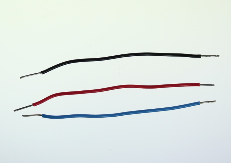
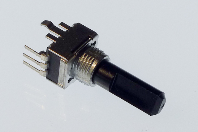
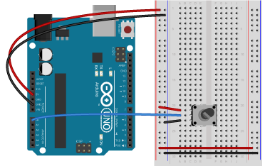
Figure 1-3 are basically what you need for this lab.

Connect the sensor
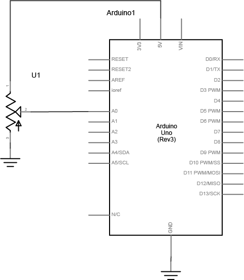
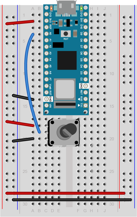
Connect your analog sensor to analog pin 0 like you did in the analog lab. A potentiometer is shown here (Figure 4-6) because it’s easy, but you might want to pick a sensor that’s more interesting. IR distance rangers are fun for this exercise, for example. Force-sensing resistors are good as well.
Read the Sensor Value and Send the Data Serially
Program the Arduino module to read the analog sensor and print the results to the Serial monitor. To do this, you’ll use the Arduino serial commands. You’ve been using these in the digital and analog labs to send data to the Serial Monitor. Instead of using the Serial.println() command as you did in those labs, however, use Serial.write(). This will send the sensor value as a raw binary value rather than as a string:
void setup() {
  Serial.begin(9600);
}

void loop() {
  int analogValue = analogRead(A0)/4; // read the sensor value
  Serial.write(analogValue);          // send the value serially as a binary value
}
Note: Why divide the sensor value by 4?
Dividing the sensor value by 4 reduces the range to 0 to 255, the range that can fit in a single byte.
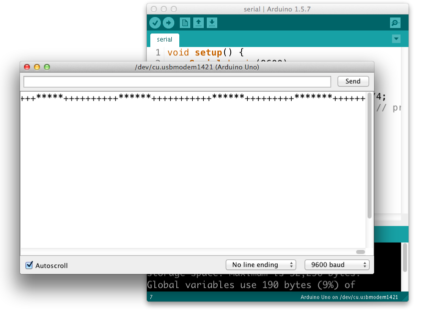
When you open the Serial Monitor, you will see garbage characters(Figure 7). What’s going on? The Serial.write() command doesn’t format the bytes as ASCII characters. It sends out the binary value of the sensor reading. Each sensor reading can range from 0 to 1023; in other words, it has a 10-bit range, since 210 = 1024 possible values. Since that’s more than the eight bits that can fit in a byte, you’re dividing the value by 4 in the code above, to get a range from 0 to 255, or 28 bits. For more background on this, see the notes on variables.
So, for example, if the sensor reading’s value is 234, then the Serial.write() command sends the binary value 11101010. If the reading is 255, then Serial.write() sends 11111111. If it’s 157, then the command sends 10011101. For more decimal-to-binary conversions, open your computer’s calculator and choose the Programmer view (press apple-3 on a mac, and Alt-3 on Windows).
When the Serial Monitor receives a byte, it and assumes it should show you the ASCII character corresponding to that byte’s value. The garbage characters are characters corresponding to the ASCII values the Monitor is receiving. You’ll learn more about that in the two-way serial lab.
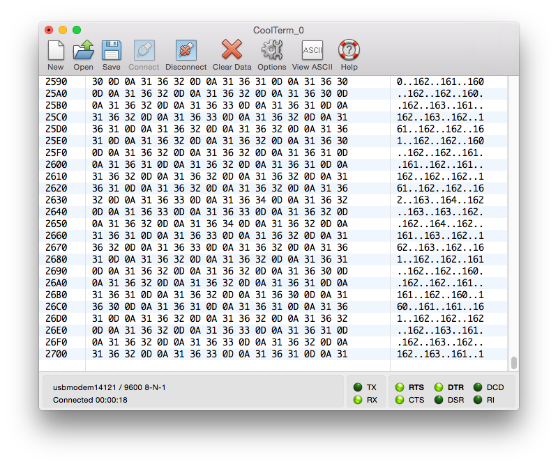
Sending data using Serial.write() is efficient for the computer, but it’s difficult to read. However, there are other ways to see the serial data. The serial terminal program CoolTerm is available for Mac, Windows, and Linux. It gives you both an ASCII view of incoming bytes and a hexadecimal view (Figure 8). Download it and install it, and open the Options tab. From there, pick your serial port in the menu, then close the Options tab. Then click the Connect button to open the serial port. Related Video: Using CoolTerm
NOTE: only one program can control a serial port at a time. When you’re not using a given program, remember to close the serial port. You won’t be able to re-program the Arduino module if you don’t, because the serial terminal program will have control of the serial port.
Once you have data coming into CoolTerm, click the Hex button. Instead of seeing the ASCII representation of the byte, you’ll see its hexadecimal value, with the ASCII characters down the side. As you change the sensor’s value, you’ll see the values change.
Remember, the microcontroller is just sending a series of electrical pulses. How those pulses are interpreted is up to the program that reads them. In CoolTerm, you see two different interpretations, the hexadecimal value and the ASCII character corresponding to the value.
For most projects, you’ll set the port settings to 9600 bits per second, 8 data bits, no parity, one stop bit, and no hardware flow control. This will be set in the Preferences or Settings or Connection Options of whatever program you’re using. Once you’ve applied those settings, open the serial port by clicking. Any bytes you type in the window will be sent out the serial port you opened. They won’t show up on the screen, however. Any bytes received in the serial port will be displayed in the window. Click the Disconnect button to close the serial port.
Read the Data in Processing
Related video: Basic Processing
The serial monitor in Arduino and CoolTerm aren’t the only programs on your computer that can read data in from the microcontroller. Any program that can access the computer’s serial ports can do it. Processing is an excellent tool for reading serial data because you can program it to interpret the data any way you want. Write a program to take in serial bytes and graph them.
The first thing you need to do is to import the Processing Serial Library. This is a code library that adds functionality to Processing so it can read from and write to the computer’s serial ports. You can do this by choosing the Sketch menu, then Import Library...-->serial, or you can type:
Processing code:
import processing.serial.*;
To use the serial library, create an instance of the library in a global variable as shown below:
Processing code:
Serial myPort;
Note: you might get an error message when trying to use the Processing Serial Library for the first time. Here are instructions on what to do if this happens.
In the setup() method, set the window size, and use the serial library to get a list of the serial ports:
Processing code:
void setup () {
  size(800, 600);        // window size

  // List all the available serial ports
  println(Serial.list());
}
If you run what you’ve typed so far, you should get a list of the serial ports in the monitor pane that looks a bit like this on a mac. On a Windows machine, the port list will have names like COM3, COM4, COM5, and so forth:
/dev/cu.Bluetooth-Incoming-Port
/dev/cu.Bluetooth-Modem
/dev/cu.usbmodem13
/dev/cu.usbmodem15
/dev/cu.usbmodem17
/dev/cu.usbmodem1421
/dev/cu.usbmodem14221
/dev/tty.Bluetooth-Incoming-Port
/dev/tty.Bluetooth-Modem
/dev/tty.usbmodem13
/dev/tty.usbmodem15
/dev/tty.usbmodem17
/dev/tty.usbmodem1421
/dev/tty.usbmodem14221
One of these ports is the same as the serial port name you use in the Arduino programming environment. That’s the one you want. In this case, it’s /dev/tty.usbmodem1421 or the 13th item in the list. But since arrays start counting at zero, that item is counted as the 12th item. So to open that port, add the following lines at the end of the setup:
Processing code:
// change the number below to match your port:
String portName = Serial.list()[12];
myPort = new Serial(this, portName, 9600);
Finally, set the background color. Pick a nice color, don’t just use primary colors. You’ll be looking at it a long time, so you might as well like it. If you can’t think of a nice color combination, try color.adobe.com. Add this to the end of the setup:
Processing code:
background(#081640);
The serial library has a special method called serialEvent(). Every time a new byte arrives in the serial port, serialEvent() is called. So you can use it to read bytes coming in the serial port from the microcontroller. Write a serialEvent method that reads the incoming byte and prints it out:
Processing code:
void serialEvent (Serial myPort) {
  // get the byte:
  int inByte = myPort.read();
  // print it:
  println(inByte);
}
myPort.read() tells the program to read a byte from the serial port myPort. Bytes are read like peas coming out of a peashooter. Every time you read a byte, it’s removed from the serial buffer. So it’s good practice to read the byte into a variable as shown above, then never read again until you want another byte. If you want to do something with the byte you read (like graphing it), use the variable in which you saved the incoming byte.
Graph the Sensor Value
Now it’s time to draw a graph with the bytes you read. To do this, you’ll pick a point whose distance from the bottom of the window corresponds to the byte’s value. In other words, the vertical position (call it yPos) equals the height minus the byte’s value (yPos = height - inByte). Add global variables called xPos and yPos and set them to 0. Then in the draw(), set the stroke color to a nice color, and draw a line at xPos, from the bottom of the screen to the vertical position you just calculated.
Add this at the top of the program:
Processing code:
// at the top of the program:
float xPos = 0; // horizontal position of the graph
float yPos = 0; // vertical position of the graph
Add this to the end of the serialEvent() method. it will change yPos based on the last byte you read from the serial port:
yPos = height - inByte;
Then add this draw() method:
Processing code:
void draw () {
  // draw the line in a pretty color:
  stroke(#A8D9A7);
  line(xPos, height, xPos, yPos);
}
Finally you need to increment the horizontal position after you draw the line, so that the next byte’s line is further along on the graph. If you reach the edge of the screen, set the horizontal position back to 0. Do this at the end of the draw():
Processing code:
// at the edge of the screen, go back to the beginning:
if (xPos >= width) {
  xPos = 0;
  // clear the screen by resetting the background:
  background(#081640);
} else {
  // increment the horizontal position for the next reading:
  xPos++;
}
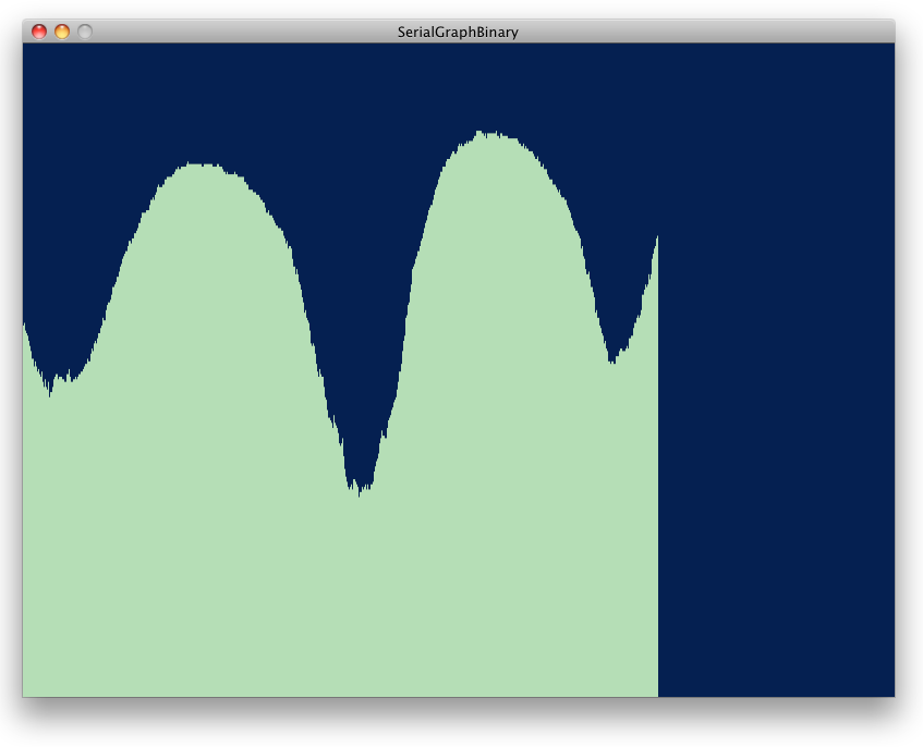
That’s it! When you run this sketch, you’ll see the sensor’s value graphed on the screen like so (Figure 9):