Introduction
This page explains the basic pin functions that most microcontrollers share, and offers some tips for switching from one microcontroller to another. Since the tutorials on this site are all written with the Arduino Uno in mind, and students may be using other controllers, you may need to know how to “convert” a tutorial from the controller it’s written for to your own controller. In order to get the most out of it, you should know something about electrical circuits, and what a microcontroller is and what it can do. This video might help: Hardware functions in a microcontroller
What Do All These Pins Do?
A typical microcontroller can have between 6 and 60 pins on it, to which you’re expected to attach power connections, input and output connections, and communications connections. Every microcontroller has different configurations for its pins, and often one pin will have more than one function. This combining of functions on one pin is called pin multiplexing.
Every microcontroller has names for the pins specific to its hardware, but the Arduino application programming interface (API) provides a set of names for pins and their functions that should work across all microcontrollers that are programmable with the API. So, for example, A0 will always be the analog input pin 0, whether you’re on an Uno, 101, MKRZero, MKR1000, or other Arduino-compatible board. When you connect to the pin with the same function on another board, your code should operate the same, even though the physical layout of pins is different.
Every board has an operating voltage that affects its pins as well. The operating voltage, which is the same as the voltage of the GPIO pins, is labeled below. If you’re connecting a component to a board with a lower voltage than the component, you’ll need to do some level shifting.
Pin Diagrams
Microcontrollers typically come in a variety of physical forms, or packages. Sparkfun has a nice tutorial on integrated circuit package types if you want to know more. Pin numbering on any integrated circuit, including microcontrollers, starts at top left corner, which is usually marked with a dot. From there, you count around the chip counter-clockwise. For modules like the Arduino Uno, this numbering doesn’t hold up, since the board has several pin headers. The pin headers are usually numbered, and the pins of each header are counted. Unfortunately, header numbering does not always follow the same patterns as IC numbering.
Microcontroller pins are referred to by their physical pin (where they are physically on the board) and their functional pin names (what they do). For example, the Arduino Nano’s physical pin 20 is digital I/O pin 2.
Arduino Nano Series
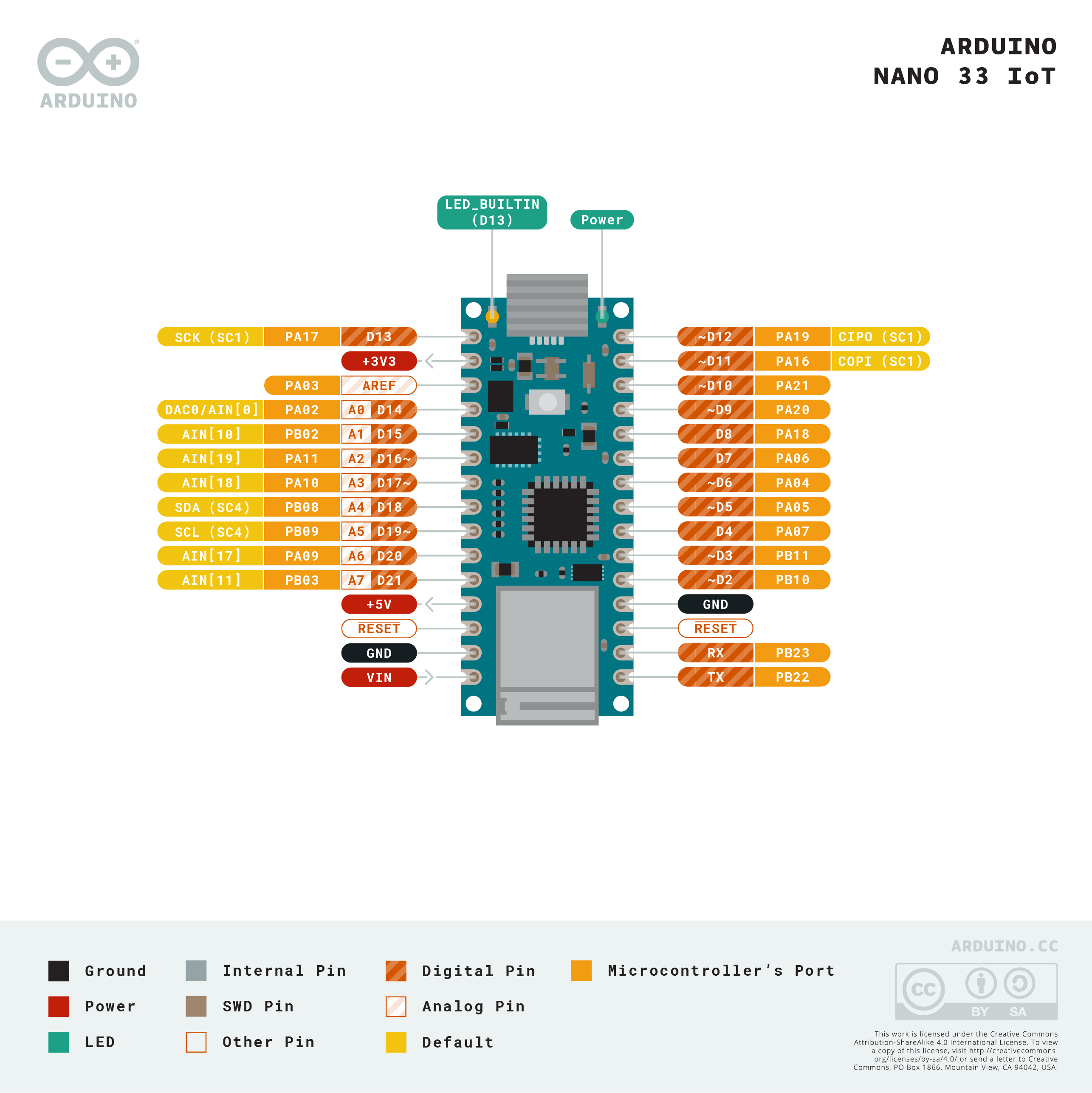
The Arduino Nano boards, like the Nano Every, Nano 33 IoT, Nano 33 BLE, Nano 33 BLE Sense, and Nano RP2040 Connect have a number of similar features. The Nano 33 IoT is shown in Figure 1, but the other Nanos have the same pin layout. The pin numbering follows the U-shaped pattern of a typical integrated circuit as described above; pin 1 is on the top left, and pin 30 is on the top right. The pins, summarized, are as follows:
- Physical pin 1: Digital I/O 13
- Physical pin 2: 3.3V output
- Physical pin 3: Analog Reference
- Physical pin 4-11: Analog in A0-A7; Digital I/O 14-21
- Physical pin 12: VUSB (not normally connected)
- Physical pin 13: Reset
- Physical pin 14: Ground
- Physical pin 15:Vin
- Physical pin 16: Digital I/O pin 1; Serial1 UART TX
- Physical pin 17: Digital I/O pin 0; Serial1 UART RX
- Physical pin 18: Reset
- Physical pin 19: Ground
- Physical pin 20-30: Digital I/O pins 2-12
PWM Pins: on the Nano 33 IoT, the following pins can be used as PWM pins: digital pins 2, 3, 5, 6, 9, 10, 11, 12, A2, A3, and A5. One pin A0, can also be used as a true analog out, because it has a digital-to-analog converter (DAC) attached. On the Nano Every, only pins 3, 5, 6, 9, and 10 can be used as PWM pins. On the Nano 33 BLE, all digital pins can be used as PWM pins.
- SPI Pins:
- SDI- digital pin 12 (physical pin 30)
- SDO – digital pin 11 (physical pin 29)
- SCK – digital pin 13 (physical pin 1)
- CS – digital pin 10 (physical pin 28)
- I2C Pins:
- SDA – pin A4 (physical pin 8)
- SCL – pin A5 (physical pin 9)
- UART Pins:
- Serial 1 TX: digital pin 1 (physical pin 16)
- Serial1 RX: digital pin 0 (physical pin 17)
Notes on the Nano Series
- The Nano Every operates on 5V. The Nano 33 IoT, 33 BLE, and RP2040 Connect operate on 3.3V.
- The Nano 33 IoT is based on the SAMD21 processor, just like the MKR boards. It has a NINA W102 radio that can communicate using Bluetooth 4.0 or WiFi, just like the MKR 1010. The RP2040 Connect has the same radio. It also has a real-time clock and an IMU sensor. For more on this board, see the Introduction to the Nano 33 IoT.
- The Nano 33 BLE is based on the nRF 52840 microcontroller. It can communicate using Bluetooth 5.0
- The Nano Every is based on the ATMega4809 microcontroller. It is functionally most similar to the Uno’s Atmega328 processor.
- The Nano RP2040 Connect is based on the Raspberry Pi RP2040 processor, a dual SAMD21 processor.
- On the Nano Every, pins 16 and 17 (TX and RX) are the serial port called Serial; they are also attached to the USB-Serial microcontroller on board. On the 33 IoT and 33 BLE, they are the serial port called Serial1 and are not attached to the USB serial port.
- On the Nano 33 IoT as opposed to other Arduino Nano boards, pins A4 and A5 have an internal pull-up resistor and default to the I2C functions.
- On the Nano 33 IoT and Nano 33 BLE, the VUSB pin does NOT supply voltage but is connected through a jumper, to the USB power input. You need to solder the jumper on the bottom of the board to use VUSB.
- Interrupts: All the Nano 33 IoT’s, Nano 33 BLE’s, and Nano Every’s digital pins can be used as hardware interrupts. However, some repeat, so check the AttachInterrupt guide for the best pins to use as interrupts.
Arduino Uno Rev 3
The Arduino Uno Rev 3, shown in Figure 1, is the classic Arduino model. The pin numbering follows the U-shaped pattern of a typical integrated circuit as described above; pin 1 is on the top left, and pin 30 is on the top right. The pins, summarized, are as follows:
- Physical pin 1: not connected
- Physical pin 2: I/O reference voltage
- Physical pin 3: Reset
- Physical pin 4: 3.3V output
- Physical pin 5: 5V output
- Physical pin 6-7: Ground
- Physical pin 8: Vin
- Physical pin 9-14: Analog in A0-A5; Digital I/O 14-19
- Physical pin 15-28: Digital I/O pin 0-13
- Physical pin 29: Ground
- Physical pin 30:Analog Reference
- Physical pin 31: I2C SDA; Digital I/O pin 18; Analog in A4
- Physical pin 32: I2C SCL; Digital I/O pin 19; Analog in A5
PWM Pins: on the Uno Rev 3, the following pins can be used as PWM pins: digital pins 3, 5, 6, 9, 10, 11.
- SPI Pins:
- SDI- digital pin 12 (physical pin 27; digital I/O pin 12)
- SDO – digital pin 11 (physical pin 26; digital I/O pin 11)
- SCK – digital pin 13 (physical pin 28; digital I/O pin 13)
- CS – digital pin 10 (physical pin 25; digital I/O pin 10)
- I2C Pins:
- SDA – pin A4 (physical pin 13 or 31; Analog in pin A4)
- SCL – pin A5 (physical pin 14 or 32; Analog in pin A5)
- UART Pins:
- Serial TX: digital pin 1 (physical pin 16)
- Serial RX: digital pin 0 (physical pin 15)
Notes on the Uno Rev 3
At the bottom center of the Uno board is a six-pin connector called the In-Circuit Serial Programming connector (ICSP). It has two rows of pins, labeled as follows:
- Top row (left to right): Reset, SCK, SDI
- Bottom row (left to right): Ground, SDO, +5V
On the top right of the Uno is another six-pin connector. The Uno has a second microcontroller on board to handle USB-to-serial communications. This is the ICSP header for that microcontroller.
The Serial port called Serial is attached to pins 0 and 1, and to the USB-Serial micrcontroller on board.
Interrupts: on the Uno rev. 3, only digital pins 2 and 3 can be used as interrupts.
Arduino MKR Series
The Arduino MKR series are intended for advanced RF applications. They have the same SAMD Cortex M0+ as the Nano 33 IoT, and a built-in rechargeable battery connector and charging circuit. Like most of the Nanos, the MKRs are 3.3V boards. There are several boards in the MKR line for different connectivity needs:
- The MKRZero has a built-in MicroSD card
- The MKR1000 and MKR1010 are WiFi boards; the MKR1010 has Bluetooth as well
- The MKR1300 and MKR1310 have LoRa and LoRaWAN connectivity
- The MKR1400 has a GSM radio
- The MKR1500 has a NB IoT 3G radio.
In addition, there are several special purpose shields for the MKR boards.
The pin numbering follows the U-shaped pattern of a typical integrated circuit as described above; pin 1 is on the top left, and pin 28 is on the top right. The pins, summarized, are as follows:
- Physical pin 1: Analog Reference
- Physical pin 2-8: Analog in A0-A6
- Physical pin 9-14: Digital I/O pin 0-5
- Physical pin 15-23: Digital I/O pin 6-14
- Physical pin 24: Reset
- Physical pin 25: Ground
- Physical pin 26: 3.3V output
- Physical pin 27: Vin
- Physical pin 28: 5V output
PWM Pins: on the MKR series, the following pins can be used as PWM pins: digital pins 0 – 8, 10, 12, analog pins A3, A4.
- SPI Pins:
- SDI- digital pin 12 (physical pin 19; digital I/O pin 10)
- SDO – digital pin 11 (physical pin 17; digital I/O pin 8)
- SCK – digital pin 13 (physical pin 18; digital I/O pin 9)
- CS – any other digital pin
- I2C Pins:
- SDA – Digital I/O pin 11 (physical pin 19)
- SCL – Digital I/O pin 12 (physical pin 20 )
- UART Pins:
- Serial TX: digital pin 14 (physical pin 21)
- Serial RX: digital pin 13 (physical pin 20)
Notes on the MKR Series
- Serial: The MKR series boards have two hardware UARTs.The first one, UART0 (aka Serial in your sketches) is attached directly to the USB port not to any pins. GPIO pins 13 and 14 are Serial1
- Battery in: LiPo, 3.7V, 700mAh min Recharging circuit on board.
- Interrupts: On the MKR series, pins 0, 1, 4, 5, 6, 7, 8, 9, A1, and A2 can be used as interrupts.
Pin Functions Explained
In order to make sense of all of this, it helps to know the general functions of a microcontroller. There are a few common functions:
Power: Every microcontroller will have connections for power (often labeled Vcc, Vdd, or Vin) and ground. A bare microcontroller will have only those, but modules like the Arduino, the Raspberry Pi, and others also have voltage regulators and other components on board. On these, it’s common to see an unregulated voltage input (Vin) and a regulated voltage output (5V and 3.3V on the Uno, for example).
Clock: Every microcontroller needs a clock. The bare microcontroller chip usually has two pins for this. On a module, the clock is usually built onto the board, and the pins are not exposed.
General Purpose Input and Output (GPIO): Most pins on a microcontroller can operate as either a digital input or digital output.
Hardware Interrupts: Many microcontrollers have a subset of their GPIO pins attached to hardware interrupt circuits. A hardware interrupt can interrupt the flow of a program when a given pin changes its state, so you can read it immediately. Some higher level functions like asynchronous serial and PWM sometimes use these interrupts. They’re also good for very responsive reading of digital inputs.
Analog Input (ADC): Not all microcontrollers have an analog-to-digital converter (ADC), but those that do have a number of pins connected to it and act as inputs to the ADC. If there are analog inputs, include analog reference pin as well, that tells the microcontroller what the default high voltage of the ADC is.
Pulse Width Modulation (PWM): Few microcontrollers have a true analog voltage output (though the MKR1000 does), but most have a set of pins connected to an internal oscillator that can produce a pseudo-analog voltage using PWM. This is how the analogWrite() function in Arduino works.
Communications:
Universal Asynchronous Receiver/Transmitter (UART): Asynchronous serial communication is managed by a Universal Asynchronous Receiver/Transmitter, or UART, inside the processor. The UART pins are usually attached to internal hardware interrupts that can interrupt the program flow when new serial data arrives, so you never miss a byte. It’s possible to manage serial communication in software alone, but at high speeds, you’ll see more errors.
Synchronous Serial: SPI and I2C: Most microcontrollers also have dedicated modules in the processor to handle the two most common forms of synchronous serial communication.
The Serial-Peripheral Interface (SPI) bus has four dedicated pins: Serial Data Out (SDO), also called Controller In, Peripheral Out (CIPO); Serial Data In (SDI), or Controller Out, Peripheral In (COPI); Serial Clock (SCK) and Chip Select (CS). Many miccrocontrollers are programmed via SPI through an In-Circuit Serial Programming header (ICSP) as well.
The Inter-Integrated Circuit (I2C) bus has two pins: Serial Data (SDA) and Serial Clock (SCL).
Reset: All microcontrollers have a pin which resets the program. Usually you take this pin low to reset the controller.
IORef: this is the operating voltage of the board. The Uno and 101 have this pin so that shields can read this voltage to adjust their own output voltages as needed. Not all shields have this functionality.