arduino_joystick_pushbuttons_schem

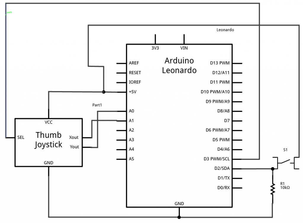
Schematic drawing of a pushbutton and a joystick attached to an Arduino Leonardo. The pushbutton is attached to digital pin 2 on one side, and to +5 volts on the other. there is also a 10-kilohm resistor attached to digital pin 2. Its other side is attached to ground. The joystick's X out pin is attached to the Leaonardo's analog input A0. The Y out is attached to analog inpug A1. The joystick's SEL (for select) output is attached to digital pin 3. The joystick's Vcc pin is connected to +5 volts. and its ground pin is connected to ground.

Schematic view of a pushbutton and a joystick attached to an Arduino Leonardo

Schematic drawing of a pushbutton and a joystick attached to an Arduino Leonardo. The pushbutton is attached to digital pin 2 on one side, and to +5 volts on the other. there is also a 10-kilohm resistor attached to digital pin 2. Its other side is attached to ground. The joystick’s X out pin is attached to the Leaonardo’s analog input A0. The Y out is attached to analog inpug A1. The joystick’s SEL (for select) output is attached to digital pin 3. The joystick’s Vcc pin is connected to +5 volts. and its ground pin is connected to ground.
Leave a Reply

Your email address will not be published. Required fields are marked *