NYU torch logo NYU | TISCH
INTERACTIVE
ITP (Grad) IMA (Undergrad) LowRes Camp
Skip to content

ITP Physical Computing

  • Syllabus
    • Syllabus Fall 2024
    • Assignments
    • Week-to-Week Activity
    • Journals & Documentation
  • Lessons
  • Videos
  • Labs
  • Resources
    • Parts And Tools Guide
    • Microcontroller Pin Functions
    • Breadboard Layouts
    • Introduction to the Nano 33 IoT
    • Construction Links
    • Related Books and Articles
    • External Links and Resources
    • Tips from Instructors
  • Pcomp @ ITP
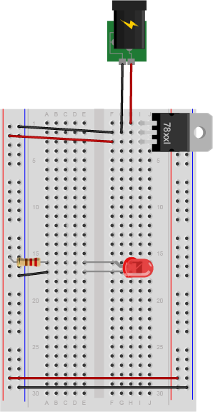
Previous Image
Next Image

led_resistor_bb

Breadboard drawing of a 220-ohm resistor and an LED powered by a 5-volt regulator . The breadboard is wired above, with a 5-volt voltage regulator and DC power jack. One side of the resistor is connected to the left side voltage bus of the breadboard. The other side is connected to row 15. The anode of an LED is connected to row 15 as well. The cathode of the LED is connected to row 16. A black wire connects row 16 to the left side ground bus.

Breadboard view of a 220-ohm resistor and an LED powered by a 5-volt regulator.

Posted on August 28, 2014August 14, 2018 Full size 298 × 577

Post navigation

Published inLab: Electronics
qr code of https://itp.nyu.edu/physcomp/labs/electronics/led_resistor_bb/
  • Syllabus
    • Syllabus Fall 2024
    • Assignments
    • Week-to-Week Activity
    • Journals & Documentation
  • Lessons
  • Videos
  • Labs
  • Resources
    • Parts And Tools Guide
    • Microcontroller Pin Functions
    • Breadboard Layouts
    • Introduction to the Nano 33 IoT
    • Construction Links
    • Related Books and Articles
    • External Links and Resources
    • Tips from Instructors
  • Pcomp @ ITP
ITP Physical Computing Proudly powered by WordPress
Accessibility