Skip to content

ITP Physical Computing

  • Syllabus Pages
    • Syllabus Fall 2025
    • Assignments
    • Week-to-Week Activity
    • Journals & Documentation
  • Lessons
  • Videos
  • Labs
  • Resources
    • Parts And Tools Guide
    • Microcontroller Pin Functions
    • Breadboard Layouts
    • Introduction to the Nano 33 IoT
    • Construction Links
    • Related Books and Articles
    • External Links and Resources
    • Tips from Instructors
  • Pcomp @ ITP
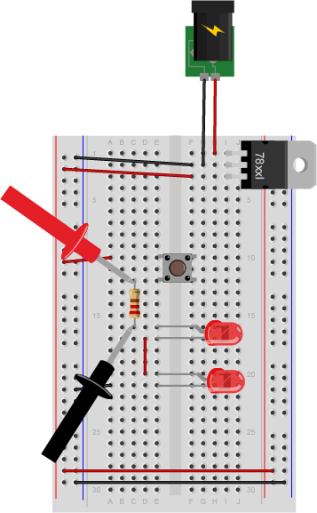
Previous Image
Next Image

measuring_voltage_resistor_bb

Breadboard drawing of a solderless breadboard as shown in the drawing above, with a 5-volt voltage regulator, a pushbutton, a 220-ohm resistor and 2 LEDs. The red probe of a multimeter is touching the side of the resistor that's connected to the pushbutton. THe black probe of the meter is touching the other side of the resistor.

Measuring voltage across a resistor in a circuit.

Posted on August 28, 2014August 14, 2018 Full size 357 × 577

Post navigation

Published inLab: Electronics
QR code of this site's URL

Find Content by Category:

  • Syllabus Pages
    • Syllabus Fall 2025
    • Assignments
    • Week-to-Week Activity
    • Journals & Documentation
  • Lessons
  • Videos
  • Labs
  • Resources
    • Parts And Tools Guide
    • Microcontroller Pin Functions
    • Breadboard Layouts
    • Introduction to the Nano 33 IoT
    • Construction Links
    • Related Books and Articles
    • External Links and Resources
    • Tips from Instructors
  • Pcomp @ ITP
ITP Physical Computing Proudly powered by WordPress