Skip to content

ITP Physical Computing

  • Syllabus Pages
    • Syllabus Fall 2025
    • Assignments
    • Week-to-Week Activity
    • Journals & Documentation
  • Lessons
  • Videos
  • Labs
  • Resources
    • Parts And Tools Guide
    • Microcontroller Pin Functions
    • Breadboard Layouts
    • Introduction to the Nano 33 IoT
    • Construction Links
    • Related Books and Articles
    • External Links and Resources
    • Tips from Instructors
  • Pcomp @ ITP
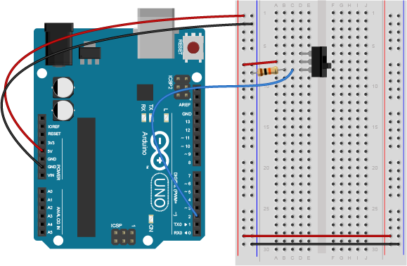
Previous Image
Next Image

LabDCMotorH-BridgeSwitch_bb

Breadboard view of a switch attached to an Arduino. The Arduino is connected to a breadboard as described in the image above. A switch is mounted in rows 4 through 6 in the left center section of the breadboard. A red wire connects from the left side voltage bus to row 7. A blue wire connects row 8 to digital pin 2 on the Arduino. a 10-kilohm resistor connects row 8 to the ground bus on the left side of the board.

Breadboard view of a switch attached to an Arduino as a digital input

Posted on August 29, 2014August 24, 2018 Full size 579 × 378

Post navigation

Published inLab: DC Motor Control Using an H-Bridge
QR code of this site's URL

Find Content by Category:

  • Syllabus Pages
    • Syllabus Fall 2025
    • Assignments
    • Week-to-Week Activity
    • Journals & Documentation
  • Lessons
  • Videos
  • Labs
  • Resources
    • Parts And Tools Guide
    • Microcontroller Pin Functions
    • Breadboard Layouts
    • Introduction to the Nano 33 IoT
    • Construction Links
    • Related Books and Articles
    • External Links and Resources
    • Tips from Instructors
  • Pcomp @ ITP
ITP Physical Computing Proudly powered by WordPress