LabJoystickNano_bb

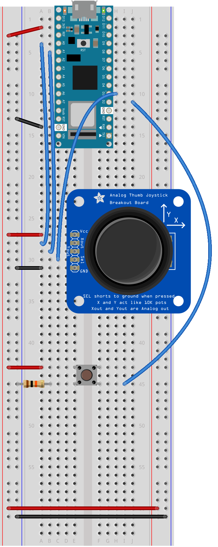
Breadboard drawing of an Arduino Nano connected to a pushbutton and a joystick. The pushbutton is described as in the previous breadboard drawing. The joystick is mounted with its five pins in rows 27 through 31 of the left center section of the breadboard. The body of the joystick is to the right of the pins, and the top pin is therefore the Vcc pin. A black wire connects row 31, the ground pin, to the left side ground bus. A red wire connects row 27, Vcc pin, to the left side voltage bus. A blue wire connects row 28, the X out pin, to the Nano's analog in pin A0. Another wire connects row 29, the Y out, to analog in A1. Yet another wire connects row 30, the Select pin, to digital pin 3.

Breadboard drawing of an Arduino Nano connected to a pushbutton and a joystick. The pushbutton is described as in the previous breadboard drawing. The joystick is mounted with its five pins in rows 27 through 31 of the left center section of the breadboard. The body of the joystick is to the right of the pins, and the top pin is therefore the Vcc pin. A black wire connects row 31, the ground pin, to the left side ground bus. A red wire connects row 27, Vcc pin, to the left side voltage bus. A blue wire connects row 28, the X out pin, to the Nano’s analog in pin A0. Another wire connects row 29, the Y out, to analog in A1. Yet another wire connects row 30, the Select pin, to digital pin 3.