We use a few different microcontroller boards in this class over the years, but for each one, there is a standard way we lay out the breadboard. This page details those layouts. In any lab exercise, you can assume the microcontroller and breadboard are laid out in this way, depending on the controller you are using. Figures 1, 2, and 3 show the layouts of an Arduino Nano 33 IoT, an Arduino Uno, an Arduino MKR.
Nano Layout
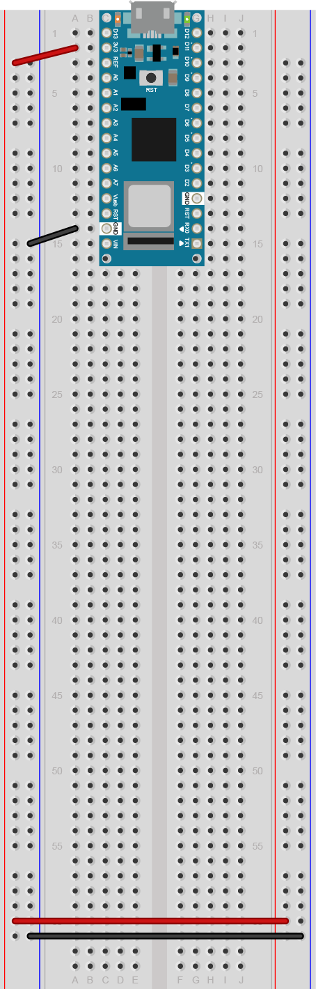
Figure 1. An Arduino Nano mounted on a solderless breadboard. The Nano is mounted at the top of the breadboard, straddling the center divide, with its USB connector facing up. The top pins of the Nano are in row 1 of the breadboard.
The Nano, like all Dual-Inline Package (DIP) modules, has its physical pins numbered in a U shape, from top left to bottom left, to bottom right to top right. The Nano’s 3.3V pin (physical pin 2) is connected to the left side red column of the breadboard. The Nano’s GND pin (physical pin 14) is connected to the left side black column.
These columns on the side of a breadboard are commonly called the buses. The red line is the voltage bus, and the black or blue line is the ground bus. The blue columns (ground buses) are connected together at the bottom of the breadboard with a black wire. The red columns (voltage buses) are connected together at the bottom of the breadboard with a red wire.
Uno Layout

Figure 2. An Arduino Uno on the left connected to a solderless breadboard, right. The Uno’s 5V output hole is connected to the red column of holes on the far left side of the breadboard. The Uno’s ground hole is connected to the blue column on the left of the board. The red and blue columns on the left of the breadboard are connected to the red and blue columns on the right side of the breadboard with red and black wires, respectively. These columns on the side of a breadboard are commonly called the buses. The red line is the voltage bus, and the black or blue line is the ground bus.
MKR Layout
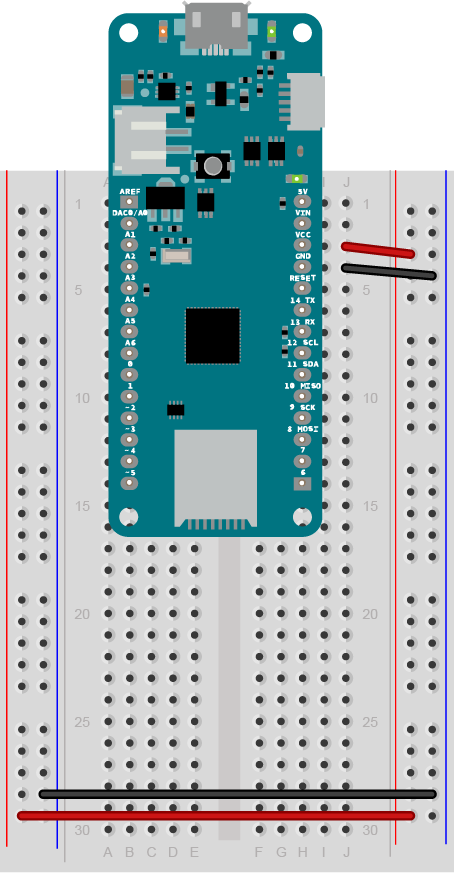
Figure 3. An Arduino MKR series board mounted on a solderless breadboard. The MKR is mounted at the top of the breadboard, straddling the center divide, with its USB connector facing up. The top pins of the MKR are in row 1 of the breadboard.
The Nano, like all Dual-Inline Package (DIP) modules, has its physical pins numbered in a U shape, from top left to bottom left, to bottom right to top right. The MKR’s Vcc pin (physical pin 26) is connnected to the right side red column of the breadboard. The MKR’s GND pin (physical pin 25) is connected to the right side black column. These columns on the side of a breadboard are commonly called the buses. The red line is the voltage bus, and the black or blue line is the ground bus.
The blue columns (ground buses) are connected together at the bottom of the breadboard with a black wire. The red columns (voltage buses) are connected together at the bottom of the breadboard with a red wire.