Skip to content

ITP Physical Computing

  • Syllabus Pages
    • Syllabus Fall 2025
    • Assignments
    • Week-to-Week Activity
    • Journals & Documentation
  • Lessons
  • Videos
  • Labs
  • Resources
    • Parts And Tools Guide
    • Microcontroller Pin Functions
    • Breadboard Layouts
    • Introduction to the Nano 33 IoT
    • Construction Links
    • Related Books and Articles
    • External Links and Resources
    • Tips from Instructors
  • Pcomp @ ITP
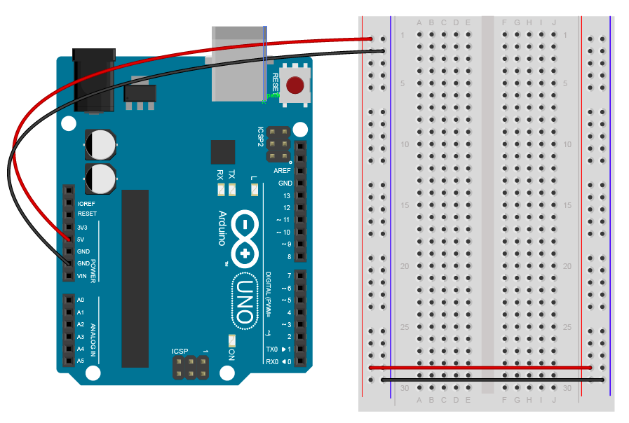
Previous Image
Next Image

LabElectronicsArduino_bb

Breadboard drawing of an Arduino Uno connected to a breadboard. The Arduino's 5V hole has a red wire connecting it to the outer left side row of the board. This is the voltage bus on the left side. The Arduino's ground hole has a black wire connecting it to the inner left side row of the board. This is the ground bus on the left side. At the bottom of the breadboard, a red wire connects the left side voltage bus to the inner row on the right side. This is the right side voltage bus. Similarly, a black wire connects the left side ground bus to the outer row on the right side. This is the right side ground bus.

An Arduino Uno connected to a breadboard. The Arduino’s 5V and ground holes are supplying voltage to the breadboard.

Posted on August 28, 2014August 10, 2018 Full size 897 × 604

Post navigation

Published inLab: Electronics
QR code of this site's URL

Find Content by Category:

  • Syllabus Pages
    • Syllabus Fall 2025
    • Assignments
    • Week-to-Week Activity
    • Journals & Documentation
  • Lessons
  • Videos
  • Labs
  • Resources
    • Parts And Tools Guide
    • Microcontroller Pin Functions
    • Breadboard Layouts
    • Introduction to the Nano 33 IoT
    • Construction Links
    • Related Books and Articles
    • External Links and Resources
    • Tips from Instructors
  • Pcomp @ ITP
ITP Physical Computing Proudly powered by WordPress