Skip to content

ITP Physical Computing

  • Syllabus Pages
    • Syllabus Fall 2025
    • Assignments
    • Week-to-Week Activity
    • Journals & Documentation
  • Lessons
  • Videos
  • Labs
  • Resources
    • Parts And Tools Guide
    • Microcontroller Pin Functions
    • Breadboard Layouts
    • Introduction to the Nano 33 IoT
    • Construction Links
    • Related Books and Articles
    • External Links and Resources
    • Tips from Instructors
  • Pcomp @ ITP
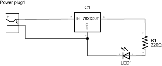
Previous Image
Next Image

led_resistor_schem

Schematic image of a 220-ohm resistor and an LED connected to a 7805 5-volt regulator. At left, there is a power plug. The positive terminal of the power plug is connected to the voltage input of a 7805 voltage regulator. The negative terminal of the power plug is connected to the ground terminal of the regulator. The voltage output of the regulator is connected to a 220-ohm resistor. The other side of the resistor is connected to the anode of an LED. The cathode of the LED is connected to the ground terminal of the regulator.

Schematic image of a 220-ohm resistor and an LED connected to a 7805 5-volt regulator.

Posted on August 28, 2014July 31, 2018 Full size 538 × 220

Post navigation

Published inLab: Electronics
QR code of this site's URL

Find Content by Category:

  • Syllabus Pages
    • Syllabus Fall 2025
    • Assignments
    • Week-to-Week Activity
    • Journals & Documentation
  • Lessons
  • Videos
  • Labs
  • Resources
    • Parts And Tools Guide
    • Microcontroller Pin Functions
    • Breadboard Layouts
    • Introduction to the Nano 33 IoT
    • Construction Links
    • Related Books and Articles
    • External Links and Resources
    • Tips from Instructors
  • Pcomp @ ITP
ITP Physical Computing Proudly powered by WordPress