NYU torch logo NYU | TISCH
INTERACTIVE
ITP (Grad) IMA (Undergrad) LowRes Camp
Skip to content

ITP Physical Computing

  • Syllabus Pages
    • Syllabus Fall 2025
    • Assignments
    • Week-to-Week Activity
    • Journals & Documentation
  • Lessons
  • Videos
  • Labs
  • Resources
    • Parts And Tools Guide
    • Microcontroller Pin Functions
    • Breadboard Layouts
    • Introduction to the Nano 33 IoT
    • Construction Links
    • Related Books and Articles
    • External Links and Resources
    • Tips from Instructors
  • Pcomp @ ITP
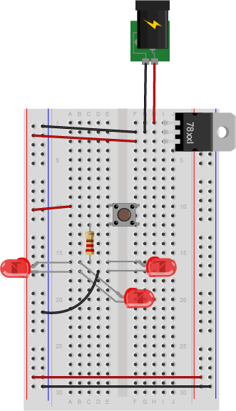
Previous Image
Next Image

leds_switch_parallel_bb

A pushbutton is mounted across the center of the breadboard, connected to rows ten and twelve. A red wire connects the switch to the left side voltage bus. A 220-ohm resistor is connected to row twelve on the left side of the center section of the board. Its other end is connected to row sixteen in the center area. Three LEDs' anodes are connected to another hole in row sixteen. The cathodes of the LEDs are connected to holes in row seventeen. A black wire connects row seventeen to the ground bus on the left side of the board.

Breadboard view of a pushbutton controlling three LEDs wired in parallel.

Posted on August 28, 2014August 14, 2018 Full size 331 × 577

Post navigation

Published inLab: Electronics
qr code of https://itp.nyu.edu/physcomp/labs/electronics/leds_switch_parallel_bb/

Find Content by Category:

  • Syllabus Pages
    • Syllabus Fall 2025
    • Assignments
    • Week-to-Week Activity
    • Journals & Documentation
  • Lessons
  • Videos
  • Labs
  • Resources
    • Parts And Tools Guide
    • Microcontroller Pin Functions
    • Breadboard Layouts
    • Introduction to the Nano 33 IoT
    • Construction Links
    • Related Books and Articles
    • External Links and Resources
    • Tips from Instructors
  • Pcomp @ ITP
ITP Physical Computing Proudly powered by WordPress