Skip to content

ITP Physical Computing

  • Syllabus Pages
    • Syllabus Fall 2025
    • Assignments
    • Week-to-Week Activity
    • Journals & Documentation
  • Lessons
  • Videos
  • Labs
  • Resources
    • Parts And Tools Guide
    • Microcontroller Pin Functions
    • Breadboard Layouts
    • Introduction to the Nano 33 IoT
    • Construction Links
    • Related Books and Articles
    • External Links and Resources
    • Tips from Instructors
  • Pcomp @ ITP
Previous Image
Next Image

measuring_resistance_bb

Breadboard drawing of measuring resistance. A breadboard circuit similar to the one above is shown, with a 5-volt regulator and DC power jack. In this circuit, a red wire connects the ledt side power bus to row 12. An LED is connected from row 15 to row 16, and a black wire connects row 16 to the left hand side ground bus. A 220-ohm resistor is off to the left side of the breadboard. It has been removed from the board to measure resistance. Two multimeter probes are attached to either end of the resistor.

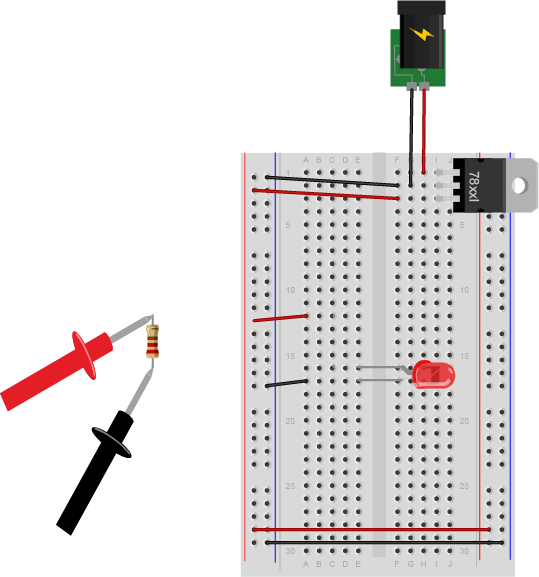
Measuring resistance. Note that this circuit is not complete. To measure a component’s resistance, you have to take it out of the circuit.

Posted on August 28, 2014August 14, 2018 Full size 539 × 577

Post navigation

Published inLab: Electronics
QR code of this site's URL

Find Content by Category:

  • Syllabus Pages
    • Syllabus Fall 2025
    • Assignments
    • Week-to-Week Activity
    • Journals & Documentation
  • Lessons
  • Videos
  • Labs
  • Resources
    • Parts And Tools Guide
    • Microcontroller Pin Functions
    • Breadboard Layouts
    • Introduction to the Nano 33 IoT
    • Construction Links
    • Related Books and Articles
    • External Links and Resources
    • Tips from Instructors
  • Pcomp @ ITP
ITP Physical Computing Proudly powered by WordPress