In this tutorial, you’ll learn how to control a servomotor’s position from a microcontroller using the value returned from an analog sensor.
Introduction
Servos are the easiest way to start making motion with a microcontroller. Servos can turn through a range of 180 degrees and you can use them to create all sorts of periodic or reciprocating motions. Check out some of the mechanisms at Rob Ive’s site for ideas on how to make levers, cams, and other simple machines for making motion. The resources section of this site has links to other sites on construction, mechanics, and kinetics as well.
What You’ll Need to Know
To get the most out of this lab, you should be familiar with the following concepts. You can check how to do so in the links below:
- What is Analog Input with Arduino
- What is an Arduino Library
Things You’ll Need

Arduino Nano 33 IoT 
Flexible jumper wires. These wires are quick for breadboard prototyping, but can get messy when you have lots of them on a board. 
A solderless breadboard with two rows of holes along each side. The . board is turned sideways so that the side rows are on top and bottom in this view. There are no components mounted on the board. 
Potentiometer 
10-kilohm resistors. These ones are 5-band resistors 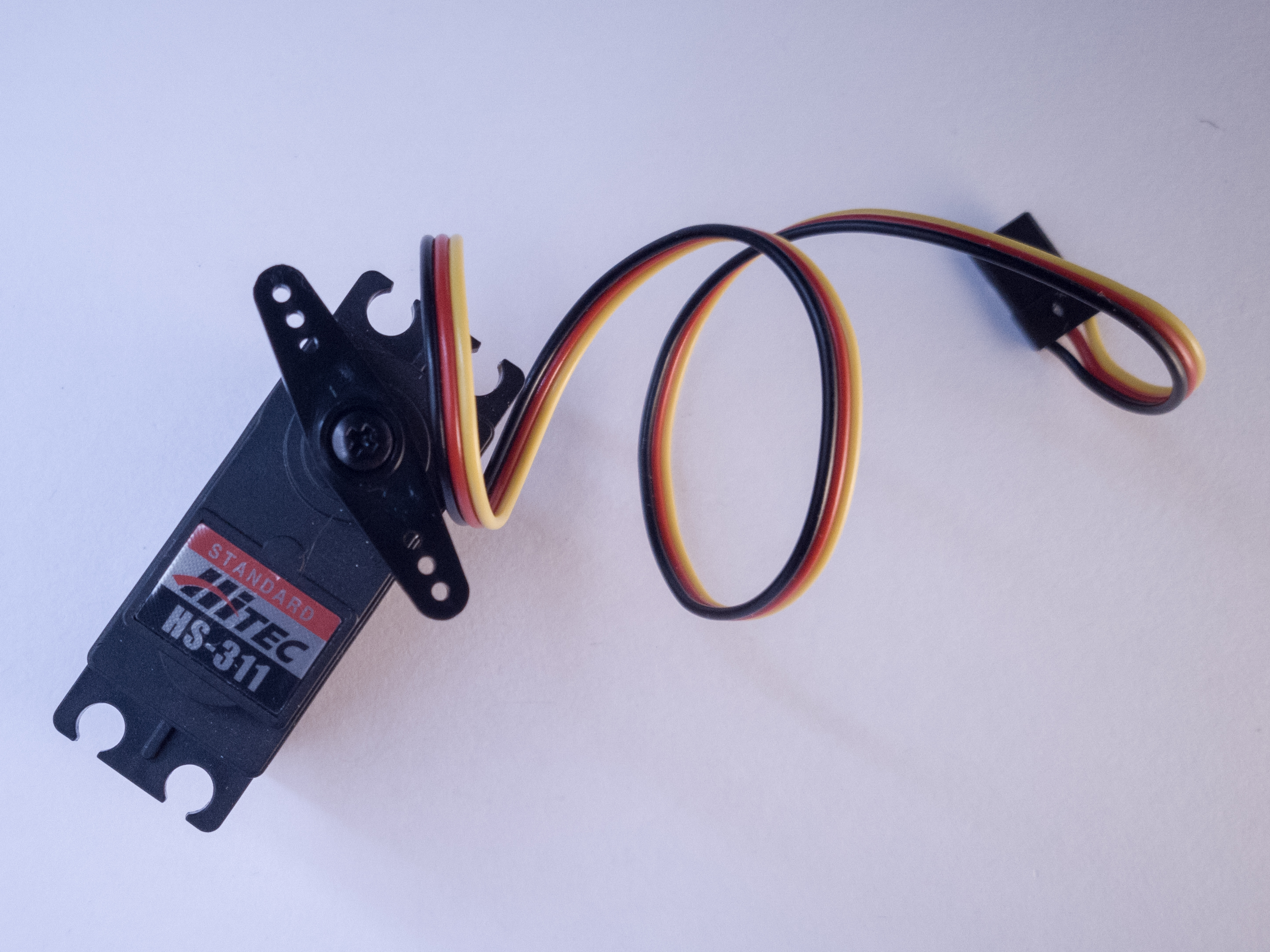
RC Servomotor 
Force Sensing Resistor (FSR) 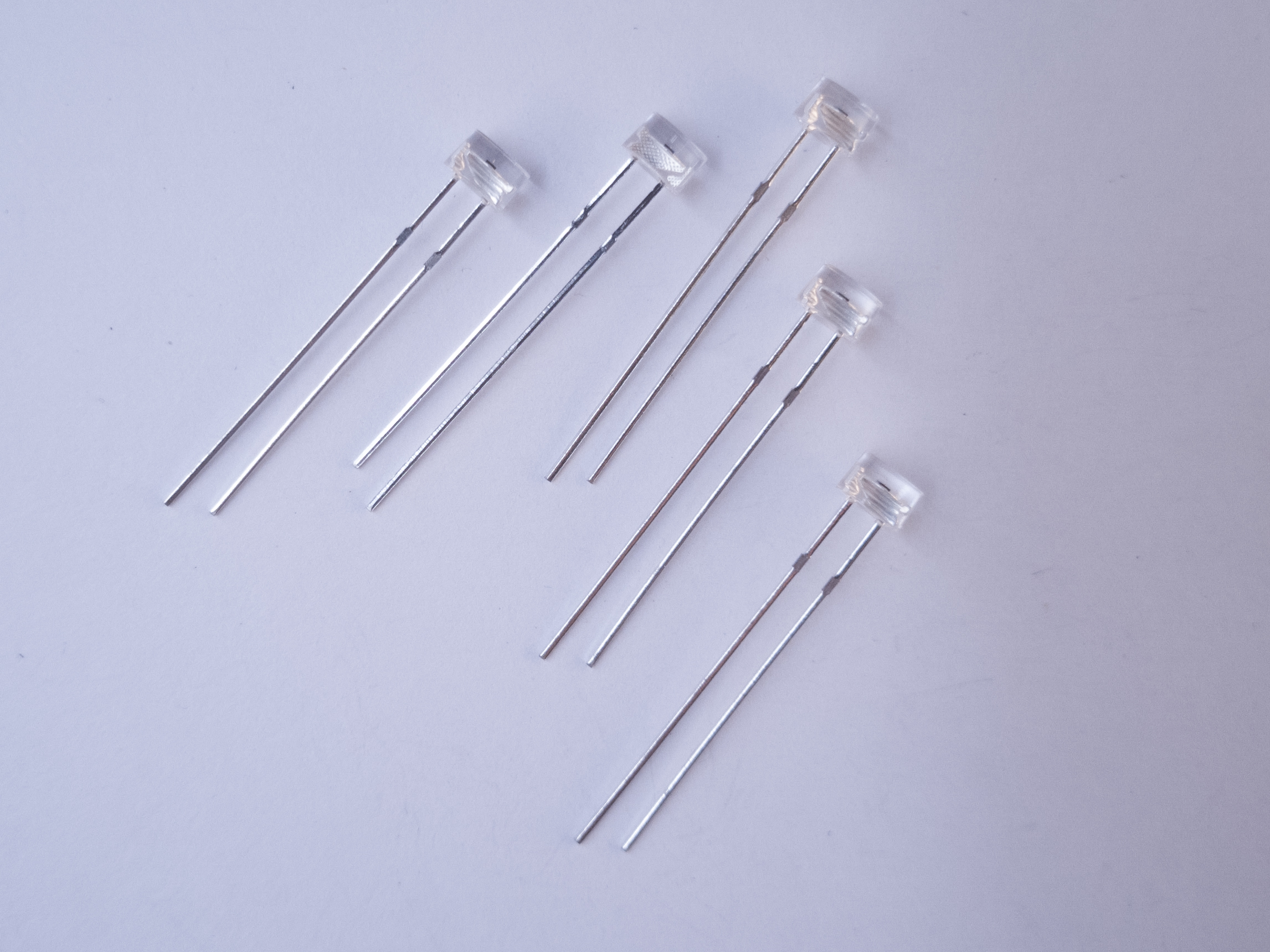
Phototransistors. The short leg goes to voltage, and the long leg goes to the input pin of a microcontroller.
Prepare the breadboard
Connect power and ground on the breadboard to power and ground from the microcontroller. On the Arduino module, use the 5V or 3.3V (depending on your model) and any of the ground connections, as shown in Figures 9 and 10.

Figure 9. An Arduino Uno on the left connected to a solderless breadboard, right. The Uno’s 5V output hole is connected to the red column of holes on the far left side of the breadboard. The Uno’s ground hole is connected to the blue column on the left of the board. The red and blue columns on the left of the breadboard are connected to the red and blue columns on the right side of the breadboard with red and black wires, respectively. These columns on the side of a breadboard are commonly called the buses. The red line is the voltage bus, and the black or blue line is the ground bus.

The Nano, like all Dual-Inline Package (DIP) modules, has its physical pins numbered in a U shape, from top left to bottom left, to bottom right to top right. The Nano’s 3.3V pin (physical pin 2) is connected to the left side red column of the breadboard. The Nano’s GND pin (physical pin 14) is connected to the left side black column. These columns on the side of a breadboard are commonly called the buses. The red line is the voltage bus, and the black or blue line is the ground bus. The blue columns (ground buses) are connected together at the bottom of the breadboard with a black wire. The red columns (voltage buses) are connected together at the bottom of the breadboard with a red wire.
Images made with Fritzing
Connect an Analog Input Sensor and a Servo
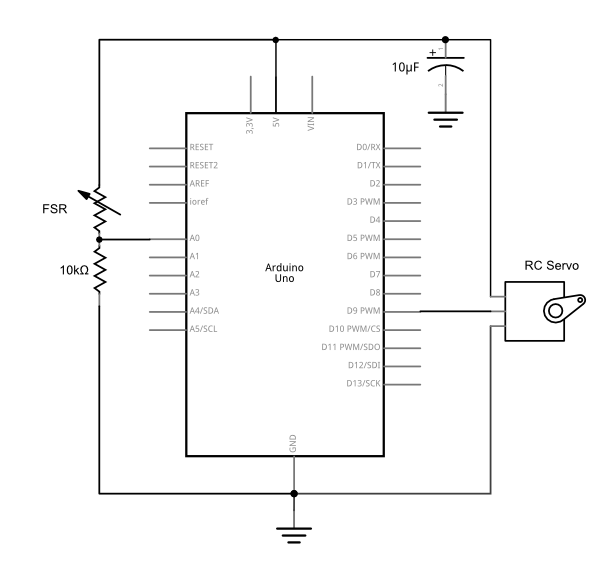
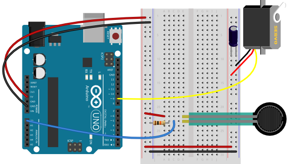
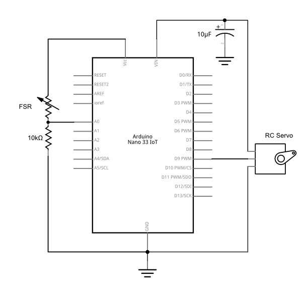
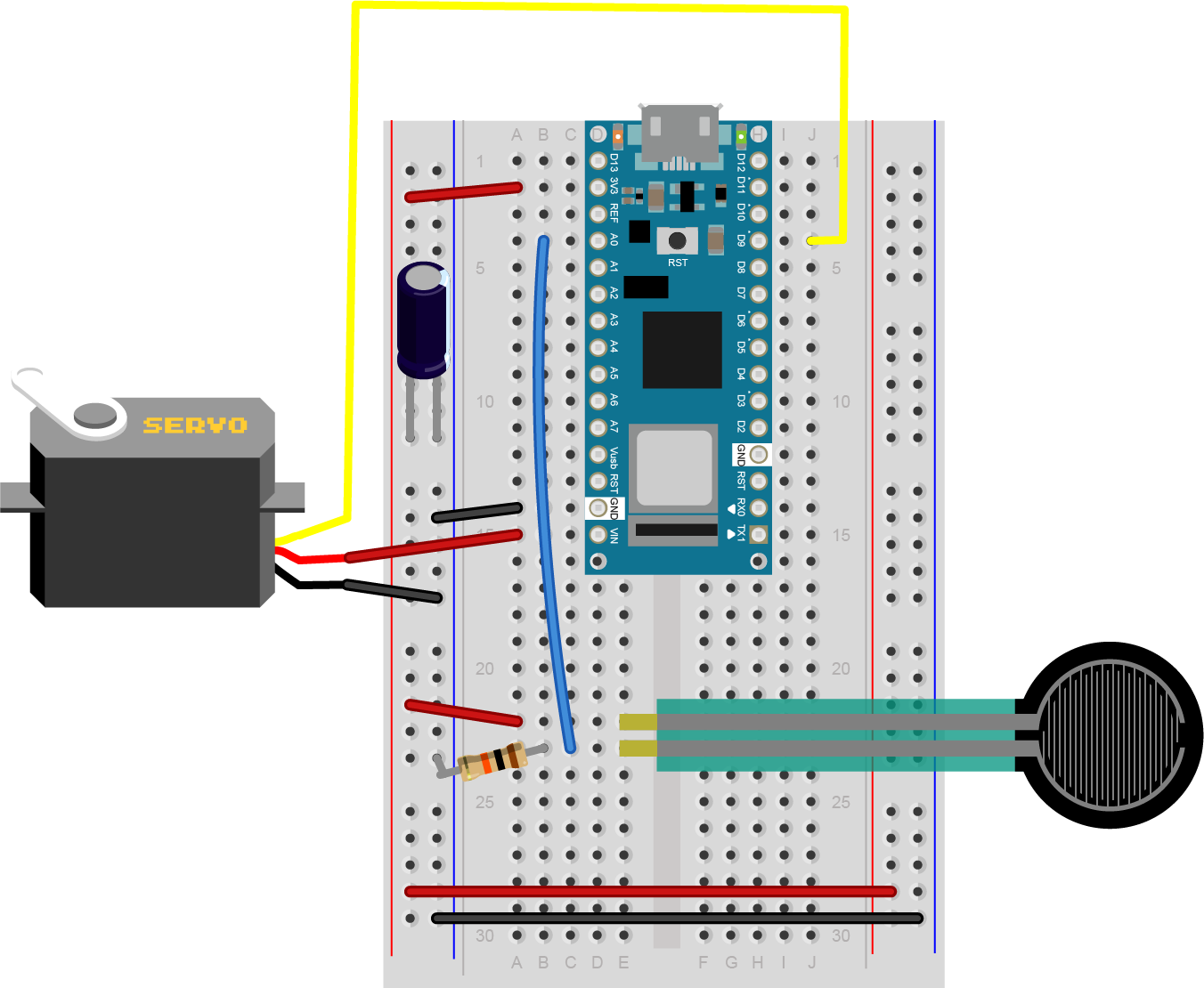
Connect an analog input to analog pin 0 as you did in the Analog Input Lab covered previously. A force-sensing resistor is shown in Figure 11-14 below, but you can also use a potentiometer, phototransistor, or any analog input you prefer. Then connect an RC servomotor to digital pin 9. The yellow wire of the servo goes to the pin, and the red and black wires go to +5V and ground, respectively.
Most RC servomotors are rated for 4-6 volt power input. When you’re using a 3.3V microcontroller like the Nano 33 IoT, you can use the Vin pin to power the motor if you’re running off USB power, or off a 5V source connected to the Vin.
Related video:Intro to Servo Motors
Safety Warning! Not all servos have the same wiring colors. For example, the Hextronik servos that come with Adafruit’s ARDX kit use red for +5V, brown for ground, and mustard yellow for control. Check the specifications on your particular servomotor to be sure.
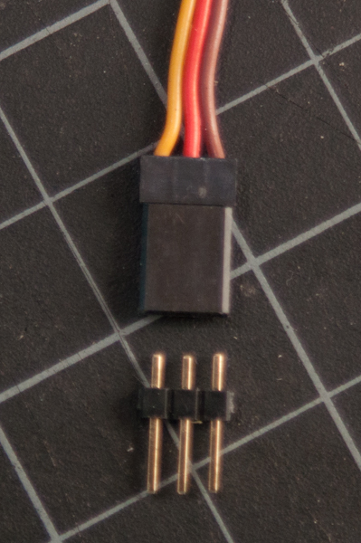
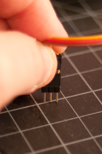
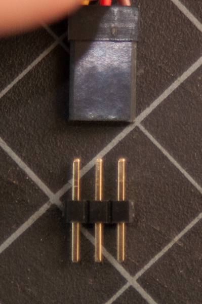
When you attach the servo, you’ll need a row of three male headers to attach it to a breadboard. You may find that the pins don’t stay in the servo’s connector holes. Put the pins in the servo’s connector, then push them down on a table gently. They will slide up inside their plastic sheaths, and fit better in your servo’s connector.
Different RC servomotors will have different current requirements. The Tower SG5010 model servo sold by Adafruit draws more current than the HiTec HS311 and HS318 sold by ServoCity, for example. The Tower Pro servo draws 100-300 mA with no load attached, while the HiTec servos draw 160-180mA. The decoupling capacitor in the circuit will smooth out any voltage dips that occur when the servo turns on, but you will need an external 5V supply if you are using more than one servomotor.
Related video: Connect the Servo
Figures 15-17 show steps of this in action.
Program the Microcontroller
First, find out the range of your sensor by using analogRead() to read the sensor and printing out the results.
void setup() {
  Serial.begin(9600);       // initialize serial communications
}

void loop()
{
  int analogValue = analogRead(A0); // read the analog input
  Serial.println(analogValue);      // print it
}
Now, map the result of the analog reading to a range from 0 to 179, which is the range of the sensor in degrees. Store the mapped value in a local variable called servoAngle.
void setup() {
  Serial.begin(9600);       // initialize serial communications
}

void loop()
{
  int analogValue = analogRead(A0); // read the analog input
  Serial.println(analogValue);      // print it

  // if your sensor's range is less than 0 to 1023, you'll need to
  // modify the map() function to use the values you discovered:
  int servoAngle = map(analogValue, 0, 1023, 0, 179);
}
Finally, add the servo library at the beginning of your code, then make a variable to hold an instance of the library, and a variable for the servo’s output pin. In the setup(), initialize your servo using servo.attach(). Then in your main loop, use servoAngle to set the servo’s position.
#include "Servo.h"      // include the servo library

Servo servoMotor;       // creates an instance of the servo object to control a servo
int servoPin = 9;       // Control pin for servo motor
// time when the servo was last updated, in ms
long lastMoveTime = 0;

void setup() {
  Serial.begin(9600);       // initialize serial communications
  servoMotor.attach(servoPin);  // attaches the servo on pin 9 to the servo object
}

void loop() {
  int analogValue = analogRead(A0); // read the analog input
  Serial.println(analogValue);      // print it

  // if your sensor's range is less than 0 to 1023, you'll need to
  // modify the map() function to use the values you discovered:
  int servoAngle = map(analogValue, 0, 1023, 0, 179);

  // move the servo using the angle from the sensor every 20 ms:
  if (millis() - lastMoveTime > 20) {
    servoMotor.write(servoAngle);
    lastMoveTime = millis();
  }
}
Related video: Code for the Servo & Turn the Servo
Get Creative
Servo motors give you the power to do all kinds of things.
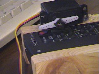
They can be used to push a remote control button, in a pinch, as shown in Figure 18.
You can play music with found objects like in this Project by Nick Yulman. You can build a frisking machine like in this project by Sam Lavigne and Fletcher Bach. If you’ve got 800 or so of them and a lot of time, you can build a wooden mirror like this Project by Daniel Rozin.