Introduction
This lab is an introduction to generating simple tones on an Arduino. In order to make the most of this lab, you should understand the basics of how to program digital input and output on an Arduino, and how to read a simple circuit diagram.
What You’ll Need


Making Sound Electronically
The following is adapted from SoundExamples.
Sound is created by vibrations in air. When those vibrations get fast enough, above about 20 times a second, you hear them as an audible pitch. The number of vibrations per second is called the frequency and frequency is measured in Hertz (Hz). So 20 times a second is 20Hz. Humans can hear pitches from about 20Hz to about 20,000Hz, or 20 kiloHertz (kHz).
What vibrations are we talking about? A speaker can vibrate. The paper cone of the speaker moves forward, then backward, then back to its resting place many times a second. The length of time it takes to move from rest through one back-and-forth motion, is called the period of the vibration. For example, if a speaker is vibrating at 20Hz, then it moves forward, backward, and back to rest 2in 1/20 of a second, or 0.05 seconds. 0.05 seconds is the period of the sound. Period and frequency are related inversely: frequency = 1/period.
A microcontroller makes sound by sending pulses of electrical energy from an output pin through a wire that’s connected to the paper cone of a speaker. That wire is wrapped in a coil, and mounted inside a magnet. The electrical energy generates a magnetic field, and that field is either attracted to the magnet or repelled by it, depending on which direction the electrical energy is flowing. The magnetic energy moves the coil, and since the coil is attached to the cone, the speaker moves.
So in summary: how do you make sound from an Arduino? Attach a speaker to an output pin and turn it on and off at a set frequency. You can write this code yourself, or you can use the tone() command.
Pulsewidth Modulation vs. Frequency Modulation
When you use analogWrite() to create pulsewidth modulation (PWM) on an output pin, you’re also turning the pin on and off, so you might think, “why not use analogWrite() to make tones?” That command can change the on-off ratio of the output (also known as the duty cycle) but not the frequency. If you have a speaker connected to an output pin running analogWrite(), you’ll get a changing loudness, but a constant tone. To change the tone, you need to change the frequency. The tone() command does this for you.
Prepare the breadboard
Connect power and ground on the breadboard to the microcontroller. On the Arduino module, use the 5V or 3.3V (depending on your model) and any of the ground connections. Figures 8 and 9 show connections for an Arduino Uno and a Nano, respectively.

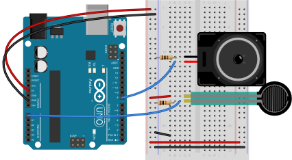
The Uno’s 5V output hole is connected to the red column of holes on the far left side of the breadboard (Figure 8). The Uno’s ground hole is connected to the blue column on the left of the board. The red and blue columns on the left of the breadboard are connected to the red and blue columns on the right side of the breadboard with red and black wires, respectively. These columns on the side of a breadboard are commonly called the buses. The red line is the voltage bus, and the black or blue line is the ground bus.

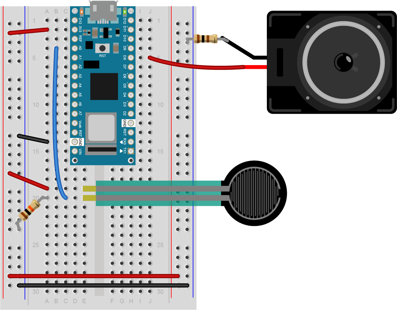
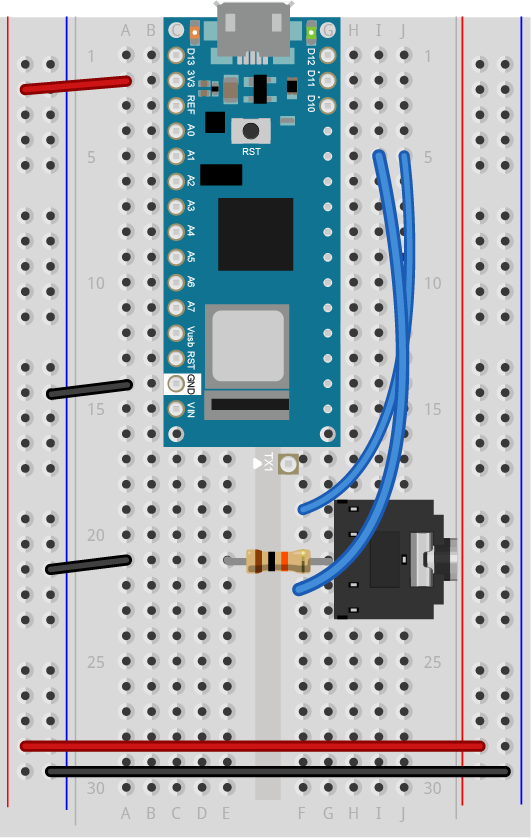
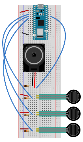
In Figure 9, the Nano is mounted at the top of the breadboard, straddling the center divide, with its USB connector facing up. The top pins of the Nano are in row 1 of the breadboard.
The Nano, like all Dual-Inline Package (DIP) modules, has its physical pins numbered in a U shape, from top left to bottom left, to bottom right to top right. The Nano’s 3.3V pin (physical pin 2) is connected to the left side red column of the breadboard. The Nano’s GND pin (physical pin 14) is connected to the left side black column. These columns on the side of a breadboard are commonly called the buses. The red line is the voltage bus, and the black or blue line is the ground bus. The blue columns (ground buses) are connected together at the bottom of the breadboard with a black wire. The red columns (voltage buses) are connected together at the bottom of the breadboard with a red wire.
Images made with Fritzing
Connect the Sensors and the Speaker
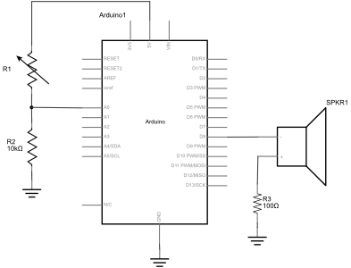
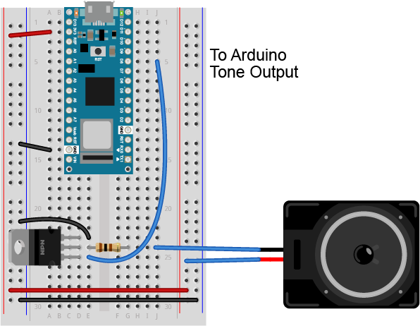
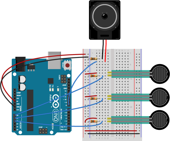
Connect a variable resistor such as a force-sensing resistor or photosensor to analog pin 0 in a voltage divider circuit as shown below. The 8-ohm speaker connects to pin 8 of the Arduino. You can use any digital I/O pin if you don’t like 8. The other end of the speaker connects to ground. Figures 10 through 12 show the schematic drawing and the breadboard layouts for an Uno and a Nano, respectively.
Note: Although the circuit shown in Figures 10-12 has a 100-ohm resistor with the speaker, you can use a larger resistor. The larger the resistor, the quieter the speaker. A 220-ohm resistor works reasonably well if you don’t have a 100-ohm resistor.
Check the sensor input range
Once you’ve got the circuit connected, check the range of the analog input and note the highest and lowest values you can reach.
void setup() {
  Serial.begin(9600);       // initialize serial communications
}

void loop() {
  int analogValue = analogRead(A0); // read the analog input
  Serial.println(analogValue);      // print it
}
Once you know the range, take note of it for when you map it to the tone range you want, as you’ll see below. The example here assumes a sensor range from 200 to 900, but your sensor range might be different.
Check that the Speaker Works
You can check that the speaker works by playing a single tone over and over. Here’s a short sketch to play middle A, 440Hz:
void setup() {
  // nothing to do here
}

void loop() {
  // play the tone for 1 second:
  tone(8, 440,1000);
  // do nothing else for the one second you're playing:
  delay(1000);
}
When you run this sketch, you should hear a tone of 44oHz, or middle A, continually. If you don’t, check to see that your speaker wiring is as shown above. If it’s too soft, try changing the 100 Ohm resistor to a smaller resistor.
Play Tones
Write a sketch to read the analog input and map the result to a range from 100 to 1000. The example below assumes your analog input circuit ranges from 200 to 900, so adjust for your actual values. Store the result in a local variable called frequency. This will be the frequency you play on the speaker. Then use the tone() command to set the frequency of the speaker on pin 8.
void setup() {
  // nothing to do here
}

void loop() {
  // get a sensor reading:
  int sensorReading = analogRead(A0);
  // map the results from the sensor reading's range
  // to the desired pitch range:
  float frequency = map(sensorReading, 200, 900, 100, 1000);
  // change the pitch, play for 10 ms:
  tone(8, frequency, 10);
  delay(10);
}
My sensor values are all crazy! I’m not getting a 200 to 900 range! Remember, you may need to find your individual sensor value ranges before you decide on the mapping range. Again, this example assumes your analog input circuit ranges from 200 to 900. You can also constrain the output range after you map it, to make sure it’s giving you only the range you want, like so:
frequency = constrain(frequency, 10, 1000); // do this after the map() command
Once you’ve uploaded this, move your hands over the photocells, and listen to the frequency change. It will change from 100 Hz to 1000 HZ, because that’s what you set in the map() command. If you want to change the frequency range, change those two numbers. See if you can get it to play a little tune.
If you want to know how to generate a tone without the tone() command, here’s the basic algorithm to play one wavelength:
void makeTone(float frequency) {
  // set the period in microseconds:
  int period = (1 / frequency) * 1000000;
  // turn the speaker on:
  digitalWrite(speakerPin, HIGH);
  // delay half the period:
  delayMicroseconds(period / 2);
  // turn the speaker off:
  digitalWrite(speakerPin, LOW);
  // delay half the period:
  delayMicroseconds(period / 2);
}
Play it Loud
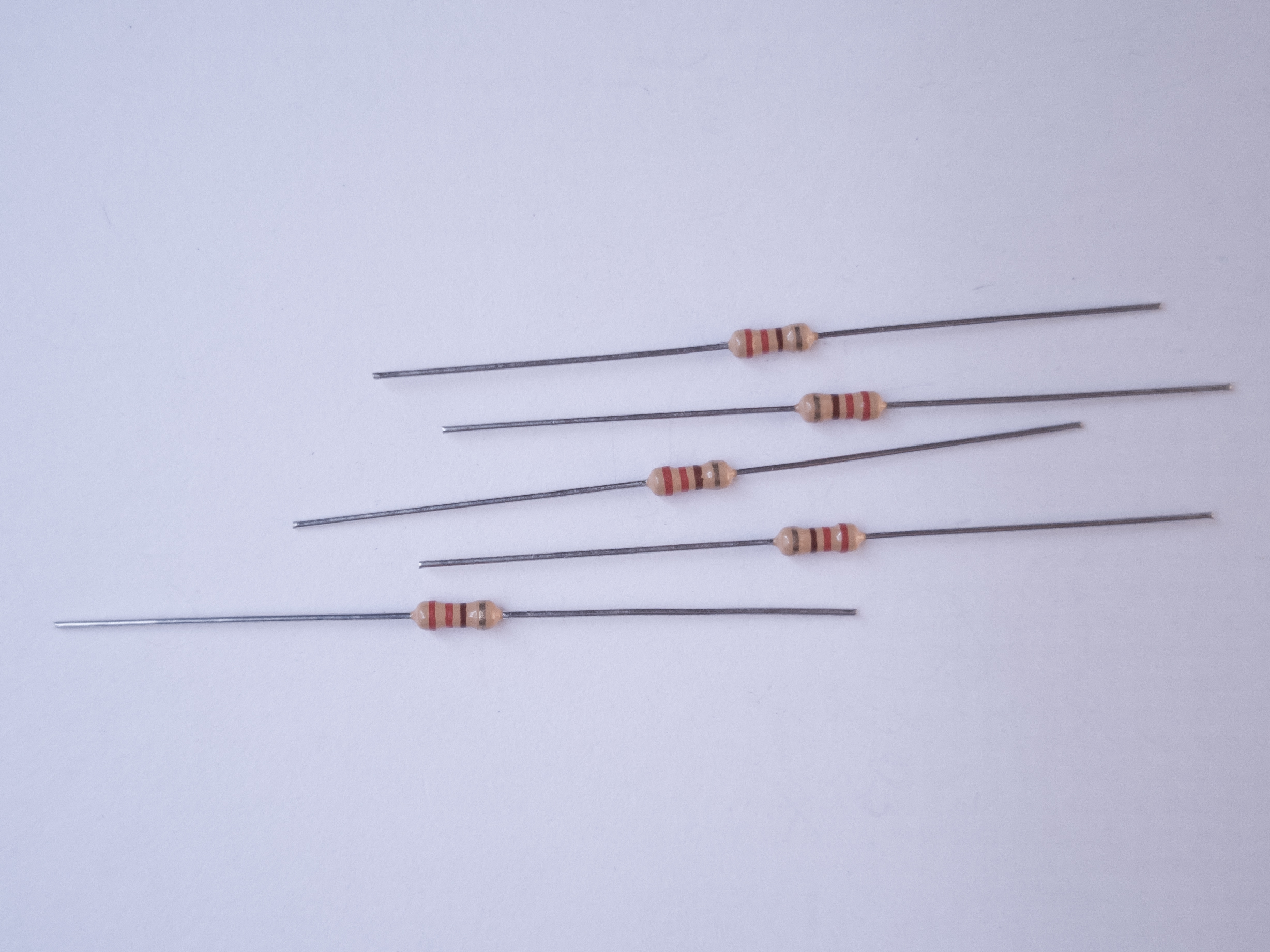
If you’d like to amplify the speaker, modify the speaker circuit by adding a transistor. Most any NPN transistor circuit or N-channel MOSFET will do. Figure 13 shows a speaker getting power from a transistor. This example uses a TIP120 transistor, but an NPN transistor or N-channel MOSFET should work. When using a transistor to amplify the power going to the speaker, you should definitely use a resistor to limit the current. A 100-ohm resistor is shown in this example.
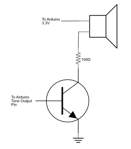
Note: the transistor shown in this circuit, a TIP120, looks the same as some of the other components you’ve used, like the 7805 regulator. When two components have the same form factor, it’s referred to as the same package. You can read more on this in the Components lab.
Use Headphones
You can also connect the tone output of an Arduino to headphones. Using a standard 3.5mm audio jack, connect the center pin of the jack to ground through a 10-kilohm resistor. Then connect the two sides to each other and to your tone output pin. The 10-kilohm resistor here is important, because without it the audio signal will be too strong for your headphones, and could cause you ear damage. Figure 15 shows an audio jack connected to an Arduino Nano 33 IoT for the examples shown here.
A more complex example
There’s an example in the Arduino IDE examples that can play a melody for you. Look in the File Menu under Examples -> Digital -> ToneMelody. You can find the code online at this link. In this example, you’ll see a second tab of text called pitches.h. This file includes constants that give you the pitches for a standard western scale.
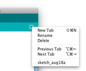
You can add your own extra tabs using the new Tab menu to the right of the IDE window. Figure 16 shows the new Tab dropdown menu. Tabs make it easier to separate frequently copied code from custom code for a sketch, as you see in this example.
You’ll notice that pitches.h lists a number of note names and numbers. Those numbers are the frequency of each note. For example:
/*************************************************
* Public Constants
*************************************************/

#define NOTE_B0  31
#define NOTE_C1  33
#define NOTE_CS1 35
#define NOTE_D1  37
#define NOTE_DS1 39
#define NOTE_E1  41
#define NOTE_F1  44
#define NOTE_FS1 46
#define NOTE_G1  49
#define NOTE_GS1 52
#define NOTE_A1  55
#define NOTE_AS1 58
#define NOTE_B1  62
#define NOTE_C2  65
#define NOTE_CS2 69
#define NOTE_D2  73
This tells you that that first note in the list, B0 (which is the second lowest note on a piano keyboard, 4 octaves below middle A) has a frequency of 31 Hz. The values listed in pitches.h allow you to play notes from B0 to D#8.
For this sketch, you’ll play a simple melody. A melody consists of notes played in a sequence, and rests between the note. Each note and rest has its own particular duration. You’re going to play a seven note sequence, as shown in Figure 17 (in C Major):
image from seventhstring.com
The sequence is: C4, G3, G3, G#3, G3, rest, B3, C4
the durations are:
quarter note, eighth note, eighth note, quarter note, quarter note, quarter rest, quarter note, quarter note.
The sketch starts with two global variables. Using pitches.h, make an array variable holding those notes. Make a second array to hold the note durations, marking quarter notes as 4 and eighth notes as 8.
// notes in the melody:
int melody[] = {
NOTE_C4, NOTE_G3,NOTE_G3, NOTE_GS3, NOTE_G3,0, NOTE_B3, NOTE_C4};

// note durations: 4 = quarter note, 8 = eighth note, etc.:
int noteDurations[] = {
4, 8, 8, 4,4,4,4,4 };
How can you use the durations to play notes? Well, imagine that a quarter note is one quarter of a second, and eighth note is one eighth of a second, and so forth. In that case, the actual duration for each note is 1000 milliseconds divided by the value for it in the durations array. For example, the first note is 1000/4, the second is 1000/8, and so forth.
Now, you only want to play the song once, so everything will happen in the setup(). You’ll make a for loop in the setup to iterate over the seven notes. For each time through the loop, use tone() to play the next note in the array. Use the formula in the last paragraph to determine how long each note should play for. After you start the note, delay for as long as the note plays, plus 30 milliseconds or so, to separate each note.
#include "pitches.h"

// notes in the melody:
int melody[] = {
NOTE_C4, NOTE_G3,NOTE_G3, NOTE_GS3, NOTE_G3,0, NOTE_B3, NOTE_C4};

// note durations: 4 = quarter note, 8 = eighth note, etc.:
int noteDurations[] = {4,8,8,4,4,4,4,4 };

void setup() {
  // iterate over the notes of the melody:
  for (int thisNote = 0; thisNote < 8; thisNote++) {
    // to calculate the note duration, take one second
    // divided by the note type.
    //e.g. quarter note = 1000 / 4, eighth note = 1000/8, etc.
    int noteDuration = 1000/noteDurations[thisNote];
    tone(8, melody[thisNote],noteDuration);
    //pause for the note's duration plus 30 ms:
    delay(noteDuration +30);
  }
}

void loop() {
  // no need to repeat the melody.
}
That’s the whole tune!
The Relation Between Pitches
For those interested in a little music theory, here’s where those frequency values in pitches.h came from. If you’re not interested in the details, feel free to skip to the next section.
You may have noticed in pitches.h that the value of B1 was twice that of B0, and that C1 is twice C0, and so forth. In European classical music tradition, the most common tuning system in the last few hundred years has been the 12-tone equal temperament system. This system divides an octave into twelve pitches, in which the frequency interval between every pair of adjacent notes has the same ratio. The pitches are arranged on a logarithmic scale, and the ratio between pitches is equal to to the 12th root of 2, or 21/12, or approximately 1.05946. The whole tuning system is based off a reference frequency, 440 Hz, or middle A (a in the 4th octave, or A4). The step between each adjacent note is called a semitone. Wikipedia’s page on equal temperament gives a longer explanation if you want to know more. Musictheory.net is also a great source of information.
You can use this information to dynamically generate notes in this scale:
frequency = 440 * 2^((noteValue - 69) / 12.0));
This formula, taken from the MIDI tuning standard, works for a range of notes. Using this formula, note 27 is A0, the lowest note on a piano, and note 108 is C8, the highest note on a piano. 440 is the reference frequency, middle A, and 69 is the note number of middle A in MIDI. With this formula, you can cover a wide range of human hearing with note values 0 to 127. And you could generate note frequencies without needing pitches.h. This formula can be handy if you decide to dive into building MIDI devices later on as well. The Arduino API includes a function called the pow() function that raises a number to a power. So that formula, expressed as a line of Arduino programming code, would look like this:
float frequency = 440 * pow(2, ((noteValue - 69) / 12.0));
And the “shave and a haircut” tune from above, would be:
int melody[] = {40, 35,35, 36, 35, 0, 39, 40};
Expressed in note values like this, it would be simple to convert a musical sketch from playing using tone() to playing using a MIDI synthesizer.
Next, try making a musical instrument.
A Musical Instrument
Playing a tune like you just doesn’t allow for much user interaction, so you might want to build more of a musical instrument.
Here’s an example of how to use the note constants to make a simple keyboard. Figures 18-20 show the circuit. Note that this can be modified to use fewer force sensing resistors if you haven’t got three of them. Or more if you have lots of them!

Program it
Make a sketch that plays a note on each sensor when the sensor is above a given threshold.
Start with a few constants: one for the threshold, one for the speaker pin number, and one for the duration of each tone. To make this instrument work, you need to know what note corresponds to each sensor. Include pitches.h as you did above, then make an array that contains three notes, A4, B4, and C3 as well. Set all of this up at the beginning of your sketch, before setup().
#include "pitches.h"

const int threshold = 10;      // minimum reading of the sensors that generates a note
const int speakerPin = 8;      // pin number for the speaker
const int noteDuration = 20;   // play notes for 20 ms

// notes to play, corresponding to the 3 sensors:
int notes[] = {
NOTE_A4, NOTE_B4,NOTE_C4 };
You don’t need anything in your setup(), but in your loop, you need a for loop that iterates over the first three analog inputs, 0, 1, and 2. For each one, read the sensor, and if it’s above a threshold, play the corresponding note in the notes array for the note duration.
#include "pitches.h"

const int threshold = 10;      // minimum reading of the sensors that generates a note
const int speakerPin = 8;      // pin number for the speaker
const int noteDuration = 20;   // play notes for 20 ms

// notes to play, corresponding to the 3 sensors:
int notes[] = {
NOTE_A4, NOTE_B4,NOTE_C4 };

void setup() {

}

void loop() {
  for (int thisSensor = 0; thisSensor < 3; thisSensor++) {
    // get a sensor reading:
    int sensorReading = analogRead(thisSensor);

    // if the sensor is pressed hard enough:
    if (sensorReading > threshold) {
      // play the note corresponding to this sensor:
      tone(speakerPin, notes[thisSensor], noteDuration);
      // delay as long as the note is playing:
      delay(noteDuration);
    }
  }
}
When you upload this sketch, you should have a three-key keyboard.
Get Creative
Now that you’ve got the basics, think about making an instrument for one of your projects. For more background on musical structure, see these notes on tone and generating a melody.
Doing More with Sound Output
If you’re interested going deeper into using sound outputs using speakers, take a look at the Mozzi Libary to produce more complex sound. In a future session, you’ll learn to play and control .wav files from Arduino, which is based on the I2S Library that connect digital audio devices together.