Introduction
In this lab, you’ll see synchronous serial communication in action using the Inter-integrated Circuit (I2C) protocol. You’ll communicate with a color, gesture, and proximity sensor from a microcontroller.
There are many different sensors on the market that use the I2C protocol to communicate with microcontrollers. It is the most common way to connect to sensors these days. The one used in this lab is typical, so the I2C principles covered here will help you when working with other I2C sensors as well.
Related videos: Intro to Synchronous Serial, I2C
What You’ll Need to Know
To get the most out of this Lab, you should be familiar with the basics of programming an Arduino microcontroller. If you’re not, review the Digital Input and Output Lab, and perhaps the Getting Started with Arduino guide. You should also understand asynchronous serial communication and how it differs from synchronous serial communication.
Things You’ll Need
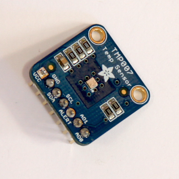
Figure 1-3 are the parts that you need for this lab.


Sensor Characteristics
The sensor used in this lab, a Broadcom APDS-9960 sensor, is an integrated circuit (IC) that can read the color of an object placed in front of it; proximity, within about 10cm; and gestures on the axes parallel to the sensor (up, down, left, and right). It senses color using four photodiodes, three of which have color filters (red, green, and blue) and one of which has no filter (clear). The color sensors are filtered to block IR and UV light. It senses gesture using four directional photodiodes, picking up reflected IR energy from a built-in IR LED. The combination of sensors is used to determine the direction of an object moving above the board, and its proximity.
The company that makes this sensor, Broadcom, doesn’t make their own breakout boards, but a few other companies do. There’s a breakout board available from Sparkfun and one from Adafruit and one from DFRobot (all available through Digikey) and there’s an APDS9960 sensor built into the Arduino Nano 33 BLE Sense board as well.
I2C Connections
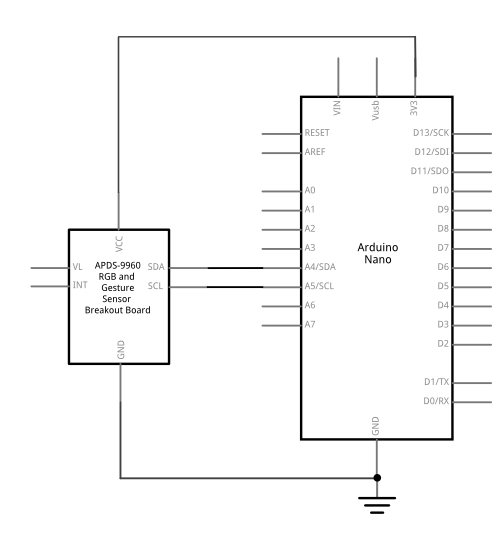
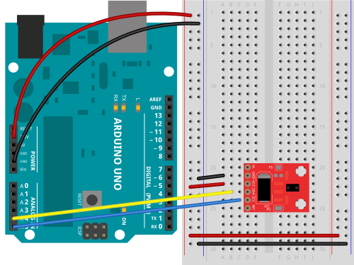
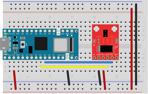
Connect the sensor’s voltage and ground connections to your voltage and ground buses, and the connections for I2C clock (SCL) and I2C serial data (SDA) as shown in Figure 4-6. The schematic, Figure 4, is the same for both the Uno and the Nano. For the Arduino Uno or the Arduino Nano boards, the I2C pins are pins A4 (SDA) and A5(SCL). This is the same connection for almost any I2C sensor.
Some I2C sensors also have a few other pins:
- an interrupt pin, which they use to signal the microprocessor when a reading is ready. The APDS-9960 has an interrupt pin, but you don’t have to use it if you don’t want to. Your code will need to change if you use the interrupt. You can read more about that later in this lab.
- a shutdown or reset pin, which can be used for powering down or resetting the sensor. This sensor doesn’t have that pin.
What are Qwiic/Stemma/Grove/Gravity?
In addition to the standard I2C connections, Sparkfun and Adafruit use a connector called Qwiic which connects the I2C, power, and interrupt connectors all in one cable, eliminating the need for soldering. It’s a Sparkfun brand name. However, you’ll need a Qwiic adapter shield to use it. Adafruit have a similar brand called Stemma, Seedstudio uses Grove, and DFRobot uses Gravity. They all support I2C, and they all have custom solderless connectors, though they are not all compatible with each other. The most compatible way is to stick with the I2C header pins.
The circuit is now complete, and you’re ready to write a program to control it. One of the advantages of the I2C synchronous serial protocol (as opposed to the SPI protocol) is that you only ever need two wires for communication to one or multiple devices.
How I2C Sensors Work
I2C devices exchange bits of data whenever the shared clock signal changes. Controller and peripheral devices both send bits of data when the clock changes from low to high (called the rising edge of the clock). Unlike with SPI, they cannot send data at the same time.
The APDS-9960 has a series of memory registers that control its function. You can write to or read from these registers using I2C communication from your microcontroller. Some of these registers are writable by the controller so that you can configure the sensor. For example, you can set set the sensitivity of the sensor, and so forth. Some registers are configuration registers, and by writing to them, you configure the chip. For example, you can set lower and upper limits of temperature sensitivity. Other memory registers are read-only. For example, when the sensor has read the proximity of an object, it will store the result in a register that you can read from the controller. The details of the chip’s registers can be found in the sensor’s datasheet.
How I2C Bits are Exchanged
Most of the time, you never have to think about how the bits of an I2C message are exchanged, and the next section, I2C Libraries, will be more important to you. For the low-level details, read on:
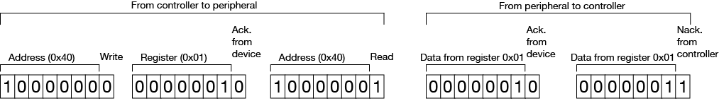
I2C devices exchange data in 7-bit chunks, using an eighth bit to signal if you’re reading or writing by the controller or for acknowledgement of data received. To get the temperature from the APDS-9960, your controller device sends the sensor’s address (a 7-bit number, for this sensor it’s 0×39) followed by a single bit indicating whether you want to read data or write data (1 for read, 0 for write). This means that the 8-bit byte sent is actually 0x72 or 0x73, depending on the state of the read/write bit. Then you send the memory register that you want to read from or write to. For example, as shown in Figure 7, the proximity reading is stored in memory register 0x9C of the APDS9960. To get the proximity, you send 0x72 (0x39 shifted up one bit, with 0 in the R/W bit); then 0x9C for the register you want to read. The response in this case is 0x77. The bottom bit is a 1, meaning no ACK was sent from the sensor. That converts to a proximity reading of 118.
I2C and the Wire Library
To use I2C communication on an Arduino microcontroller, you use the Wire library, which is built into the Arduino IDE. You can find Arduino-compatible libraries for many devices that use the Wire library, but never expose it directly in their APIs. The libraries for this sensor are typical of this style of library. For example, the Arduino_APDS9960 library’s readColor() command sends a write command to start a reading of the sensor’s color photodiodes. The colorAvailable() sends a read command to read the register that indicates whether or not the color reading is done.
All sensors take a certain amount of time to read the physical phenomena which they sense. With light-based sensors like the APDS-9960, the time they take to get a reading is usually called integration time, and it’s noted in the data sheet how long it is (page 4). The color sensor of the APDS-9960 has an integration time of between 2.78ms and 708ms, depending on your settings. In operation, you query the sensor as to whether it’s got a reading available, and then read it when that’s true.
How To Pick a Library
Most every company that makes a breakout board for a given I2C sensor will also write a library for it. For example, there’s the Arduino_APDS9960, the SparkFun_APDS9960, and the Adafruit_APDS9960 library. All three of these will work with any of the three breakout boards. The Arduino Nano 33 BLE sense will only work with the Arduino_APDS9960 library. Otherwise, what’s the difference?
Different companies and programmers have different styles for writing a library’s application programming interface, or API. Arduino has a style guide for writing APIs, but it’s not always followed by others. The Arduino_APDS9960 library follows this guide, and has the simplest API of the three. The Sparkfun_APDS9960 offers a few more configuration functions, as does the Adafruit_APDS9960, and their examples are a bit more complicated as a result. You should look at the examples with any library to see if they make sense to you. A good guideline is to use the library with the instructions and examples that you find to be the clearest. It’s also good to check the company’s guide to the sensor if they have one. Here are the guides for this sensor: Sparkfun Hookup guide; Adafruit guide; Arduino library reference.
You can also get information from the library’s header file. The header file is generally the file with the name libraryname.h. Sometimes it’s in a directory called src. For example, here’s the header file for the Arduino_APDS9960 library. Here’s the one for the Sparkfun library and the one for the Adafruit library. Within the header file, there’s a class names for the library and a section called public where all the possible function definitions are.
Even if the examples don’t include all the functions, the public section of the header file will. From there, you can build your own examples if the library’s examples don’t show how to use a function you want to use.
All three libraries operate in more or less the same way, because they have to access the same functions of the sensor. They start the function (color, proximity, or gesture) using an enable function in the setup. In the main loop, they query the sensor if it’s got a reading, and then read it if it does. For example, to use the color function, the Arduino and Adafruit libraries have functions that check if the sensor’s got a good reading: colorDataReady() in the Adafruit library and colorAvailable() in the Arduino library. The Sparkfun has no function like this, so you have to add a delay between color readings.
The Sparkfun and Adafruit libraries provide functions to explicitly enable or disable the sensor’s three major functions. The Arduino library does this work implicitly by enabling each function when you call the available() functions, and disabling the function after each read. The former give you more control, but require you to make sure you’ve done the enabling and disabling. The latter is more automatic, but gives you less discrete control.
Install the External Libraries
You can use the library manager to find these libraries. Make sure you’re using Arduino version 1.8.9 or later. From the Sketch menu, choose Include Library, then Manage Libraries, and search for APDS9960. All three of the libraries mentioned here will show up. The examples below use the Arduino_APDS9960 library, as it’s the simplest of the three.
Program the Microcontroller
At the beginning of your code, include the appropriate libraries. In the setup(), initialize the sensor with a function called begin() (Sparkfun sometimes uses init() instead of begin()). If the sensor responds, then begin() will return true, and if not, it will return false. This is how to check that the sensor is properly wired to your microcontroller:
#include "Arduino_APDS9960.h"

void setup() {
  Serial.begin(9600);
  // wait for Serial Monitor to open:
  while (!Serial);
  // if the sensor doesn't initialize, let the user know:
  if (!APDS.begin()) {
    Serial.println("APDS9960 sensor not working. Check your wiring.");
    // stop the sketch:
    while (true);
  }

  Serial.println("Sensor is working");
}
In the main loop() function, you’ll read the sensors. Here’s how to read the color sensor using the Arduino_APDS9960 library. You’re going to query the sensor to see if it’s got a reading available with the available() function, then you’ll use the read() function to get the result:
void loop() {
  // red, green, blue, clear channels:
  int r, g, b, c;

  // if the sensor has a reading:
  if (APDS.colorAvailable()) {

    // read the color
    APDS.readColor(r, g, b, c);

    // print the values
    Serial.print(r);
    Serial.print(",");
    Serial.print(g);
    Serial.print(",");
    Serial.print(b);
    Serial.print(",");
    Serial.println(c);
  }
}
You can run this sketch now, and it will print out values for red, green, blue, and clear channels, like so (Here’s a link to the full sketch):
Sensor is working
17,12,16,40
17,12,16,41
17,12,16,41
17,12,16,41
17,12,16,41
17,12,16,40
16,12,16,40
16,11,15,39
As you can see, you’re never actually calling commands from the Wire library directly, but the commands in the sensor’s library are relying on the Wire library. This is a common way to use the Wire library to handle I2C communication. If you’re looking for more examples with this sensor, the libraries all come with examples when you install them. There are some other examples for this sensor in the github repository for this class, using all three libraries. There are two important things to note:
- None of the three libraries give light readings in lux, or proximity readings in millimeters.
- All of the libraries are controlling the same sensor, and therefore can yield the same results. You may need to configure the sensor differently for each library though. Check the header files for each library (Arduino, Adafruit, Sparkfun) to learn their configuration functions, and check the data sheet to learn more about the sensor’s characteristics.
Using the Sensor’s Interrupt
Most I2C sensors include an interrupt pin. This pin can be used to signal the microcontroller when something important happens, like when the sensor has a good reading, or when the sensor reading crosses a particular threshold. Using the interrupt means that as soon as the sensor is ready to give you a reading, it interrupts the microcontoller.
The interrupt pin for an I2C sensor is usually configurable through the sensor’s API. For example, with the Sparkfun and Adafruit libraries for this sensor you can set the interrupt to signal when any of the three functions changes significantly, and with the Sparkfun library you can set the low and high thresholds for the proximity function.
For basic use of most sensors, you don’t need the interrupt, for for advanced use, it can be helpful. For more on using interrupts, see the Arduino reference page on interrupts.
Conclusion
I2C is a common protocol among many ICs, and it’s handy because you can combine many devices on the same bus. You need to make sure the device addresses are unique. Some devices will have fixed addresses, so that you can’t use multiples of the same sensor together. Others will have a way to change the address. For the APDS9960, the address is fixed.
I2C can also be used to combine several Arduinos on a bus, with one as the controller and the others as peripherals. If you build your own Arduino-compatible circuit on a breadboard, this can be an inexpensive way to combine several controllers in a more complex project. There are examples this in the Wire library documentation on the Arduino site.