Introduction
In this lab, you’ll see synchronous serial communication in action using the Inter-integrated Circuit (I2C) protocol. You’ll communicate with an infrared temperature sensor chip from a microcontroller in order to read the temperature of an object in front of the sensor.
Related videos: Intro to Synchronous Serial, I2C
What You’ll Need to Know
To get the most out of this Lab, you should be familiar with the basics of programming an Arduino microcontroller. If you’re not, review the Digital Input and Output Lab, and perhaps the Getting Started with Arduino guide. You should also understand asynchronous serial communication and how it differs from synchronous serial communication.
Things You’ll Need
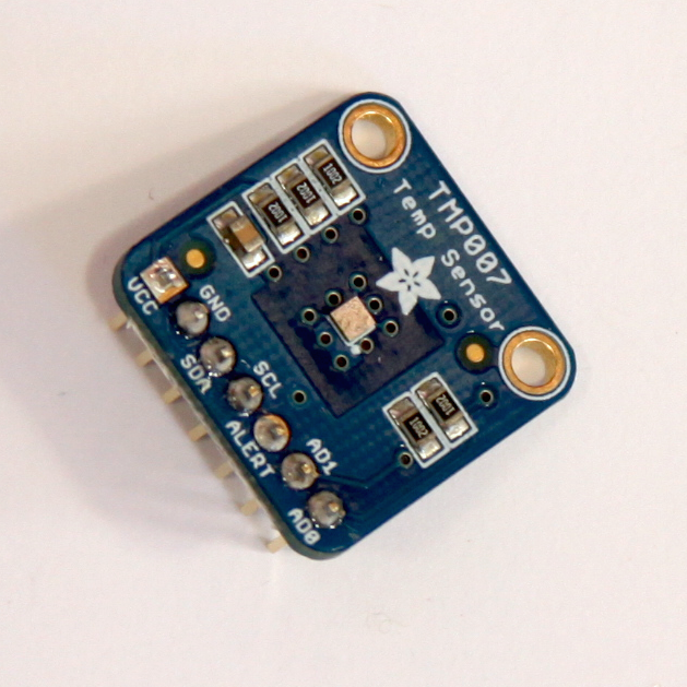
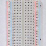
Figure 1-3 are the parts that you need for this lab.


Connect the temperature sensor
The temperature sensor used in this lab, a Texas Instruments TMP007, is an integrated circuit (IC) that can read the temperature of an object placed in front of it. Connect the sensor’s power and ground connections and the connections for clock and serial data as shown in Figure 5-7. For the Arduino UNO board and Nano boards, the I2C pins are fixed A4(SDA) and A5(SCL):
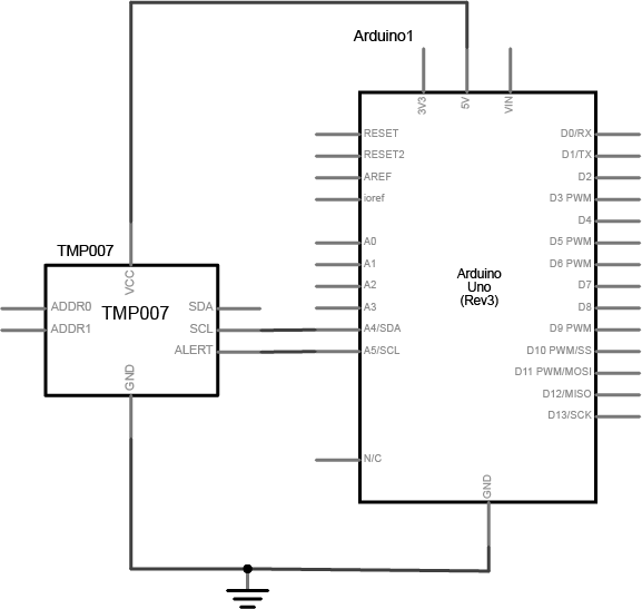
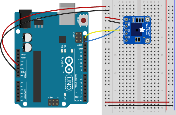
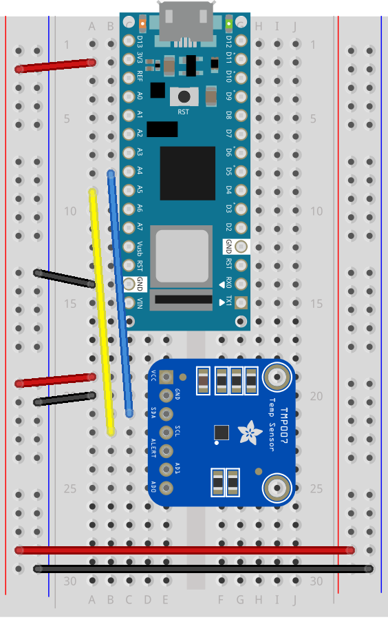
The circuit is now complete, and you’re ready to write a program to control it. One of the advantages of the I2C synchronous serial protocol (as opposed to the SPI protocol) is that you only ever need two wires for communication to one or multiple devices.
How the Temperature Sensor Works
I2C devices exchange bits of data whenever the shared clock signal changes. Controller and peripheral devices both send bits of data when the clock changes from low to high (called the rising edge of the clock). Unlike with SPI, they cannot send data at the same time.
The TMP007 has a series of memory registers that control its function. You can write to or read from these registers using I2C communication from your microcontroller. Some of these registers are writable by the controller so that you can configure the sensor. For example, you can set its I2C address, set the sensitivity of the sensor, and so forth. Some registers are configuration registers, and by writing to them, you configure the chip. For example, you can set lower and upper limits of temperature sensitivity. Other memory registers are read-only. For example, when the sensor has read the temperature of an object, it will store the result in a register that you can read from the controller. The details of the chip’s registers can be found in the TMP007 datasheet, in the “Register Maps” section, page 26.
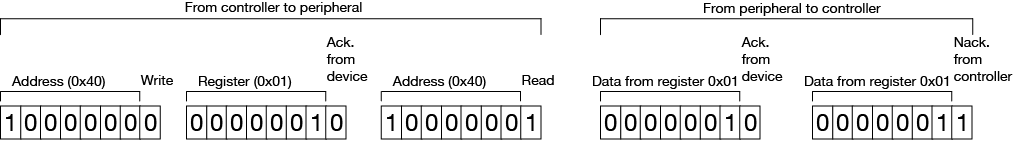
I2C devices exchange data in 7-bit chunks, using an eighth bit to signal if you’re reading or writing by the controller or for acknowledgement of data received. To get the temperature from the TMP007, your controller device sends the sensor’s address (a 7-bit number) followed by a single bit indicating whether you want to read data or write data (1 for read, 0 for write). Then you send the memory register that you want to read from or write to. For example, as shown in Figure 7, the object temperature is stored in memory register 01 of the TMP007. To get the temperature, you send:
To use I2C communication on an Arduino microcontroller, you use the Wire library, which is built into the Arduino IDE. You can find Arduino-compatible libraries for many devices that use the Wire library, but never expose it directly in their APIs. Adafruit’s TMP007 library is typical of this style of library. The library’s readObjTempC() command sends a write command to start a temperature reading of the object in front of the sensor, then sends a read command to read the appropriate temperature register, then combines the results using a formula explained in the datasheet on page 25, then returns the result to you as degrees celsius. Similarly, the readDieTempC() sends a write command to read the chip temperature, then a read command to read the appropriate temperature register, then does the math and gives you the result.
Install the External Libraries
The TMP007 library relies on the Adafruit Sensor library in addition to the Wire library, so you’ll need both in order to make this work. You can use the library manager to find these libraries or download the TMP007 library here and the Sensor library here. Make sure you’re using Arduino version 1.5.5 or later.
Once you’ve downloaded the libraries, change the name of the resulting .zip file to remove the words -master or _Library-master from the end of the file name. Keep the .zip extension though. Open the Arduino IDE (version 1.6.8 or later) and choose the Sketch menu, then choose Import Library… and finally click the Add Library… option. A dialog box will pop up asking you to find the library you want to add. Navigate to the .zip file for the Sensor library and choose it. The library will be added and you’ll see the words “Library added to your libraries. Check the ‘Import Library’ menu”.
Program the Microcontroller
At the beginning of your code, include the appropriate libraries. In the setup(), initialize the sensor with begin(). If the sensor responds, then begin() will return true, and if not, it will return false. This is how to check that the sensor is properly wired to your microcontroller:
#include "Wire.h"
#include "Adafruit_TMP007.h"

Adafruit_TMP007 tmp007; // instance of the sensor library

void setup() {
  Serial.begin(9600);
  boolean sensorInitialized = tmp007.begin(); // initialize the sensor

  while (!sensorInitialized) {
    // Do nothing until sensor responds
    Serial.println("Sensor is not responding");
  }
}
The TMP007 can only read every four seconds. In the main loop, set up an if statement to check when the millis() passes another four seconds using the modulo operator:
void loop() {
  if (millis() % 4000 < 2) { // if 4 seconds have passed
  }
}
Inside that if statement, read the object temperature and the chip temperature and print them both out:
void loop() {
  if (millis() % 4000 < 2) { // if 4 seconds have passed
    float objectTemp = tmp007.readObjTempC(); // read object temperature
    float chipTemp = tmp007.readDieTempC(); // read chip temperature

    // print the results:
    Serial.print("Chip temperature: ");
    Serial.print(chipTemp);
    Serial.print(" deg. C. \t Object temperature: ");
    Serial.print(objectTemp);
    Serial.println(" deg. C");
  }
}
As you can see, you’re never actually calling commands from the Wire library directly, but the commands in the TMP007 library are relying on the Wire library. This is a common way to use the Wire library to handle I2C communication.
Conclusion
I2C is a common protocol among many ICs, and it’s handy because you can combine many devices on the same bus. You need to make sure the device addresses are unique. Each device will have its own way to change the address. For the TMP007, see Table 2 in the data sheet; you have to set the address pins (AD1 and AD0 on the breakout board appropriately to change the address.
I2C can also be used to combine several Arduinos on a bus, with one as the controller and the others as peripherals. If you build your own Arduino-compatible circuit on a breadboard or use boards like the Adafruit Trinket or Trinket Pro, this can be an inexpensive way to combine several controllers in a more complex project. There are examples this in the Wire library documentation on the Arduino site.