Skip to content

ITP Physical Computing

  • Syllabus Pages
    • Syllabus Fall 2025
    • Assignments
    • Week-to-Week Activity
    • Journals & Documentation
  • Lessons
  • Videos
  • Labs
  • Resources
    • Parts And Tools Guide
    • Microcontroller Pin Functions
    • Breadboard Layouts
    • Introduction to the Nano 33 IoT
    • Construction Links
    • Related Books and Articles
    • External Links and Resources
    • Tips from Instructors
  • Pcomp @ ITP
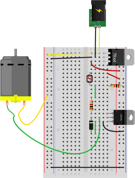
Previous Image
Next Image

LabHighCurrentLoadVDivider_bb

Breadboard drawing of a transistor controlling a DC motor with a pushbutton. The drawing is similar to the breadboard drawing with the potentiometer, but the potentiometer has been removed and a light-dependent resistor is now in rows 6 and 9 in the right center section, A fixed 10-kilohm resistor connects row 9 to the ground bus on the right side. A green wire connects row 9, to row 12 where it connects to the transistor's 1-kilohm resistor.

Breadboard drawing of a transistor controlling a DC motor with a voltage divider.

Posted on August 31, 2014August 23, 2018 Full size 440 × 577

Post navigation

Published inLab: Using a Transistor to Control a High Current Load
QR code of this site's URL

Find Content by Category:

  • Syllabus Pages
    • Syllabus Fall 2025
    • Assignments
    • Week-to-Week Activity
    • Journals & Documentation
  • Lessons
  • Videos
  • Labs
  • Resources
    • Parts And Tools Guide
    • Microcontroller Pin Functions
    • Breadboard Layouts
    • Introduction to the Nano 33 IoT
    • Construction Links
    • Related Books and Articles
    • External Links and Resources
    • Tips from Instructors
  • Pcomp @ ITP
ITP Physical Computing Proudly powered by WordPress