Introduction
In the serial output from Arduino to Processing lab, you sent data from one sensor to a personal computer. In this lab, you’ll send data from multiple sensors to a program on a personal computer. You’ll use the data from the sensors to create a pointing-and-selecting device (i.e. a mouse).
These videos will help in understanding this lab:
- Video: Two-way Serial Communication (Call-and-Response)
- Video: Reading Serial Strings in Processing
- Video: Sending and Reading Multiple Serial Values in Processing
What You’ll Need to Know
To get the most out of this Lab, you should be familiar with how to program an Arduino, and with the basics of serial communication. If you’re not, review the links below:
Things You’ll Need
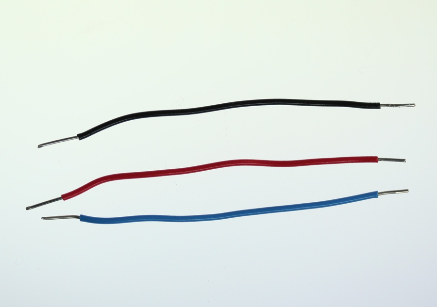
From Figure 1-5 are basically what you need for this lab.


Connect the sensors
Connect two analog sensors to analog pins 0 and 1 like you did in the analog lab. Connect a switch to digital pin 2 like you did in the digital lab.
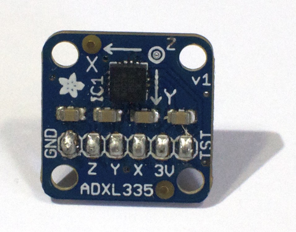
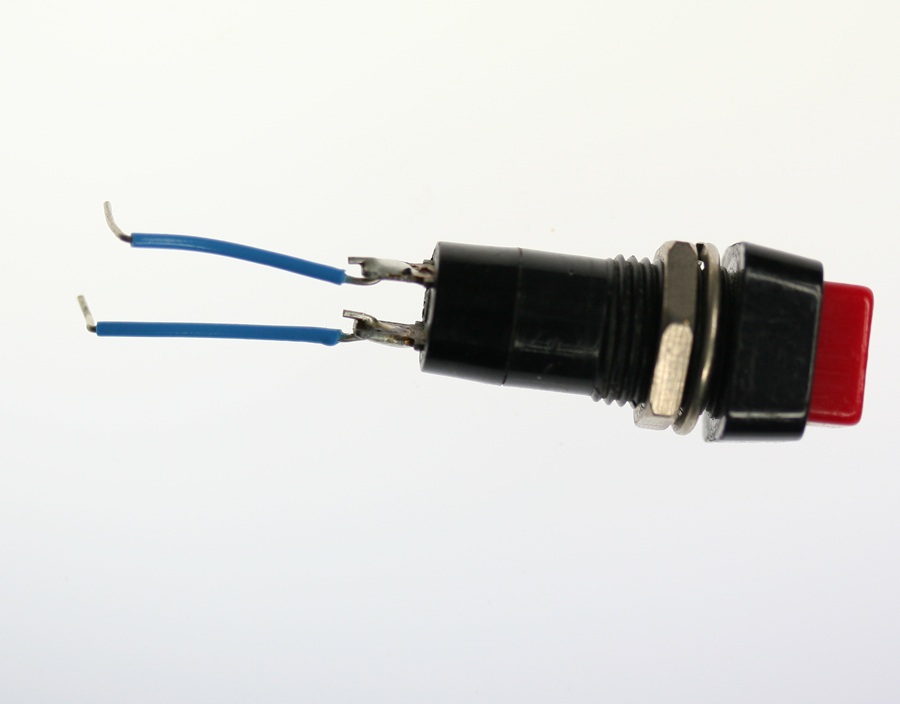
The photos and schematic in this lab show an accelerometer (Figure 6) and a pushbutton (Figure 7). You don’t have to use these, though. Use whatever sensors are appropriate to your final application. While you’re figuring what sensors to use, use the most convenient sensors you’ve got in hand; perhaps two potentiometers for the analog sensors and a pushbutton?
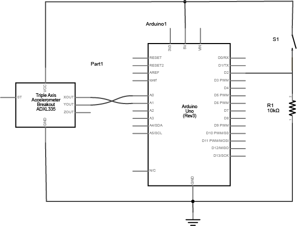

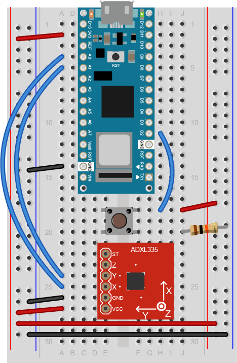
Figure 8: Breadboard view of an Arduino Nano connected to a pushbutton and an ADXL3xx accelerometer. The Nano is connected as usual, straddling the first fifteen rows of the breadboard with the USB connector facing up. Voltage (physical pin 2) is connected to the breadboard’s voltage bus, and ground (physical pin 14) is connected to the breadboard’s ground bus. The pushbutton straddles the middle of the board below the Nano. One pins of the pushbutton is connected to the voltage bus of the board. The other is connected to ground through a 10-kilohm resistor. The junction between the pushbutton and the resistor is connected to digital pin 2 of the Nano (physical pin 20). The accelerometer is connected to six rows in the left center section of the board below the pushbutton. Its Vcc pin is connected to the voltage bus, and its ground pin is connected to the ground bus. The X axis pin is connected to the Nano’s analog in 0 (physical pin 4) and the Y axis pin is connected to the Nano’s analog in 1 (physical pin 5).
(Diagram made with Fritzing)
Note: Not all accelerometers are the same. However, Analog Electronics makes a very popular series of accelerometers, the ADXL3xx series, that have three analog outputs for X, Y, and Z acceleration. This schematic should work interchangeably for most of them.
Read and send the serial data
To begin with, just send the value from one sensor, the first analog sensor (the first axis of the accelerometer in the photos) and divide the output to give a maximum value of 255:
void setup() {
  // start serial port at 9600 bps:
  Serial.begin(9600);
}

void loop() {
  // read analog input, divide by 4 to make the range 0-255:
  int analogValue = analogRead(A0)/4;
  Serial.println(analogValue);
}
When you open the serial monitor, you should see a number between 0 and 255 scrolling down the window. That’s because Serial.println() formats the value it prints as an ASCII-encoded decimal number, with a linefeed at a carriage return at the end. Also, the serial monitor assumes it should show you the ASCII character corresponding to each byte it receives.
Try changing the Serial.println() to a Serial.write(). Now you get a range of garbage characters. What’s going on?
The write() command doesn’t format the bytes as ASCII. It sends out the raw binary value of the byte. The Serial Monitor receives that binary value and assumes it should show you the ASCII character corresponding to that value again. The garbage characters are characters corresponding to the ASCII values the Monitor is receiving.
But you already knew that from the serial output from Arduino To Processing lab, didn’t you?
For example, imagine that analogValue = 32:
- Serial.println(analogValue) results in “32” with a linefeed and carriage return
- Serial.write(analogValue) results in ” “, the space character, which has the ASCII value 32.
How many bytes does Serial.println(analogValue) send when analogValue = 32?
Serial.println(analogValue) actually sends FOUR bytes! It sent a byte to represent the 3, a byte to represent the 2, a byte to tell the Monitor to move the cursor down a line (newline), and a byte to move the cursor all the way to the left (carriage return). The raw binary values of those four bytes are 51 (ASCII for “3”), 50 (ASCII for “2”), 10 (ASCII for “newline”), and 13 (ASCII for “carriage return”). Check the ASCII table and you’ll see for yourself.
Send the data in many formats
Try this program and view the results in the Serial Monitor (video link):
void setup() {
  // start serial port at 9600 bps:
  Serial.begin(9600);
}

void loop() {
  // read analog input, divide by 4 to make the range 0-255:
  int analogValue = analogRead(A0) / 4;
  Serial.println(analogValue);

  // print different formats:
  Serial.write(analogValue);  // Print the raw binary value
  Serial.print('\t');             // print a tab
  // print ASCII-encoded values:
  Serial.print(analogValue, BIN); // print ASCII-encoded binary value
  Serial.print('\t');             // print a tab
  Serial.print(analogValue);      // print decimal value
  Serial.print('\t');             // print a tab
  Serial.print(analogValue, HEX); // print hexadecimal value
  Serial.print('\t');             // print a tab
  Serial.print(analogValue, OCT); // print octal value
  Serial.println();               // print linefeed and carriage return
}
You should get output like this:
â 11100010 226 E2 342
á 11100001 225 E1 341
á 11100001 225 E1 341
á 11100001 225 E1 341
à 11100000 224 E0 340
à 11100000 224 E0 340
ß 11011111 223 DF 337
ß 11011111 223 DF 337
ß 11011111 223 DF 337
This sketch is printing the raw binary value, then the ASCII-encoded binary value, then the ASCII-encoded decimal, hexadecimal, and octal values. You may never need all of these different formats, but you’ll likely need at least the decimal and the raw binary versions at some point.
Send the values for all three sensors
If you prefer to read serial input in a command line interface, that will work here as well.
In the first serial lab, you sent one byte representing one sensor’s value, over and over. When you’re sending multiple sensor values, it gets a little more complicated. You need to a way to know which value represents which sensor. For example, imagine if you used the following loop to send your sensor values:
void loop() {
  for (int thisSensor = 0; thisSensor < 3; thisSensor++) {
    int sensorValue = analogRead(thisSensor);
    Serial.print(sensorValue);
    Serial.print(",");
  }
}
You’ll get a string like this:
452,345,416,234,534,417,325,452,231
How can you tell which value corresponds to which sensor? You don’t know which sensor is which. You could assume that if you start listening when the microcontroller starts sending that the first reading corresponds to the first sensor, but you can’t know that for sure. There are two ways to get your sensor values in order. You can use punctuation or you can use a call-and-response or handshaking method. Use whichever makes the most sense to you. They’re explained below.
Punctuation Method
One way to send the data such that it can be interpreted clearly is to punctuate each set of data uniquely. Just as a sentence ends with a period, you can end your data with a carriage return and a newline. Change the for loop above so that a carriage return and newline are printed at the end of each string of three values.
void loop() {
  for (int thisSensor = 0; thisSensor < 3; thisSensor++) {
    int sensorValue = analogRead(thisSensor);
    Serial.print(sensorValue);
    // if you're on the last sensor value, end with a println()
    // otherwise, print a comma
    if (thisSensor == 2) {
      Serial.println();
    } else {
      Serial.print(",");
    }
  }
}
From this loop, you’d get output like this:
452,345,416
234,534,417
325,452,231
This is much better. Whenever you get a newline, you know that the next value is the first sensor.
Now write a program that reads the two analog sensors on your board and the one digital switch, and prints them out in this format:
analog1, analog2, switch
analog1, analog2, switch
analog1, analog2, switch
Start by setting up a constant for the switch pin’s number. Then in the setup, initialize serial communications at 9600bps, and declare the switch pin as an input.
const int switchPin = 2;      // digital input

void setup() {
  // configure the serial connection:
  Serial.begin(9600);
  // configure the digital input:
  pinMode(switchPin, INPUT);
}
In the main loop, use a local variable called sensorValue to read each input. Read the two analog inputs first, and print them with a comma after each one. Then read the digital input, and print it with a carriage return and linefeed at the end.
void loop() {
  // read the sensor:
  int sensorValue = analogRead(A0);
  // print the results:
  Serial.print(sensorValue);
  Serial.print(",");

  // read the sensor:
  sensorValue = analogRead(A1);
  // print the results:
  Serial.print(sensorValue);
  Serial.print(",");

  // read the sensor:
  sensorValue = digitalRead(switchPin);
  // print the results:
  Serial.println(sensorValue);
}
Once you’ve got a data format, all you have to do is read it in the receiving program.
Receive the data in Processing
Now write a Processing sketch that reads the data as formatted by the Arduino program above.
First, set up the beginning of your program as you did in the first serial lab, to import the serial library and make a global variable to hold an instance of it. Then in the setup(), print out a list of serial ports, and put the one you want in a string. Then instantiate the serial library in the global variable you made.
Warning: you might get an error message when trying to use the Processing Serial Library for the first time. If this happens: inn Processing 2.0 and beyond, there is an item in the Tools menu, “Fix the Serial Library” that fixes the serial library. Test it by deleting /var/lock/ and running the Processing serial sketch again, it should now work!
Processing Code:
Add one extra line at the end of the setup() method. This line tells the sketch not to call serialEvent() unless an ASCII newline byte (value 10) comes in the serial port. It will save any other bytes it gets in the serial buffer, so you can read them all at once when the newline arrives:
Processing Code:
The draw() method doesn’t do anything, just like the first serial lab:
Processing Code:
Now your serialEvent() method only occurs when you get a newline, so you can assume that the entire string that came before the newline is in the serial buffer. Read the string, and check to see if it’s null. If it isn’t, print it out. This way, you’ll be sure you’ve got a full string before you do anything with it.
Processing Code:
The Serial.println() in Arduino attaches a newline and a carriage return. Newlines, carriage returns, spaces, and tabs are often called whitespace and there’s a command that removed whitespace from a string, called trim(). Replace the println() with the following two lines. The first trims the whitespace characters off. The second splits the string into three separate strings at the commas, the converts those strings to integers (related video: convert Strings to Floats):
Next, print out those three integers using a for() loop, like so:
Run the sketch now and you should get output like this:
Sensor 0: 510 Sensor 1: 499 Sensor 2: 0
Sensor 0: 510 Sensor 1: 498 Sensor 2: 0
Sensor 0: 510 Sensor 1: 498 Sensor 2: 0
Sensor 0: 510 Sensor 1: 497 Sensor 2: 0
Sensor 0: 509 Sensor 1: 498 Sensor 2: 0
Sensor 0: 510 Sensor 1: 497 Sensor 2: 0
Now you’ve got all the sensor values as integers, and you can do whatever you want with them. Use them to move a circle on the screen. To do that, you’ll need a few global variables at the beginning of the sketch:
Add a line at the beginning of the setup() to set the window size:
Put the following lines in the draw method. These will draw the circle using the variables you just declared:
In order to see anything happen, you need to assign the sensor values to these variables. Do this at the end of the serialEvent():
If you run this, you should see the ball moving onscreen whenever you press the switch and move the analog sensors. If your analog values are greater than 800 or 600, the ball will be offscreen, so you may have to map your sensor range to the screen size. For example, the accelerometer sensor ranges are approximately 430 to 580. Since the screen is 0 to 800 (horizontal) and 0 to 600 (vertical), map the ranges of the sensors to fill the screen.
Call and Response (Handshaking) Method
Another way to keep multiple bytes of serial data in order is to send one set of values at a time, rather than sending repeatedly. If you use this method, the receiving program has to request new data every time it finishes reading what it’s got.
You can convert the punctuation method shown above to a call-and-response method fairly simply. First, modify the Arduino code. Add a new method at the end of the sketch called establishContact(). This method sends out a message on startup until it gets a byte of data from Processing. Later you’ll modify the Processing sketch to look for this message and send a response:
void establishContact() {
  while (Serial.available() >= 0) {
    Serial.println("hello");   // send a starting message
    delay(300);
  }
}
To call this, add a line at the end of the setup() method:
establishContact();
Now, modify the loop() by adding an if() statement to look for incoming serial data and read it.
void loop() {
  if (Serial.available() > 0) {
    // read the incoming byte:
    int inByte = Serial.read();
    // read the sensor:
    sensorValue = analogRead(A0);
    // print the results:
    Serial.print(sensorValue);
    Serial.print(",");

    // read the sensor:
    sensorValue = analogRead(A1);
    // print the results:
    Serial.print(sensorValue);
    Serial.print(",");

    // read the sensor:
    sensorValue = digitalRead(switchPin);
    // print the results:
    Serial.println(sensorValue);
  }
}
The rest of the Arduino sketch remains the same. When you run this and open the serial monitor, you’ll see:
hello
hello
hello
hello
Type any character in the output box and click Send. You’ll get a string of sensor values at the end of your hellos:
510,497,0
Type another character and click Send. It doesn’t matter what character you send, but the loop will always wait for an incoming byte before sending a new set of sensor values.
Next modify the Processing program. Add a new global variable called firstContact before the setup():
Then modify the serialEvent(). Until firstContact is true, the serialEvent() will look for the “hello” message from the microcontroller. When it gets the initial message, it will send out a byte to request data. From then on, it will read in the string, parse it, and send a byte to request more data when it’s done.
If you did everything right, the ball should move in response to the analog sensors, and appear or disappear when you press the button.
Advantages of Raw Binary vs. ASCII
All the examples shown here sent the sensor values as ASCII-encoded strings. As mentioned above, that means you sent three bytes to send a three-digit value. If that same value was less than 255, you could send it in one raw binary byte. So ASCII is definitely less efficient. However, it’s more readable for debugging purposes, and if the receiving program is well-suited to convert strings to numbers, then ASCII is a good way to go. If the receiver’s not so good at converting strings to numbers (for example, it’s more challenging to read a multiple byte string in Arduino than in Processing) then you may want to send your data as binary values.
Advantages of Punctuation or Call-and-Response
The punctuation method for sending multiple serial values may seem simpler, but it has its limitations. You can’t easily use it to send binary values, because you need to have a byte with a unique value for the punctuation. In the example above, you’re using the value 10 (ASCII newline) as punctuation, so if you were sending your sensor values as raw bytes, you’d be in trouble when the sensor’s value is 10. The receiver would interpret the 10 as punctuation, not as a sensor value. In contrast, call-and-response can be used whether you’re sending data as raw binary values or as ASCII-encoded values.
Sometimes the receiver reads serial data slower than the sender sends it. For example, if you have a program that does a lot of graphic work, it may only read serial data every few milliseconds. The serial buffer will get full in that case, you’ll notice a lag in response time. This is when it’s good to switch to a call-and-response method.
Get creative
You just duplicated the basic functionality of a mouse; that is, a device with two analog sensors that affect X and Y, and a digital sensor (mouse button). What applications can you think of that could use a better physical interface for a mouse? A video editor that scrubs forward and back when you tilt a wand? An action game that reacts to how hard you hit a punching bag? An instructional presentation that speeds up if you shift in your chair too much? A music program driven by a custom musical instrument that you design
Create a prototype in Arduino and Processing, or whatever programming environment you choose. Come up with a physical interface that makes it clear what actions map to what movements and actions. Figure out which actions can and should be possible at the same time.