Introduction
From the first digital I/O and analog labs, you’ve been using asynchronous serial communication in order to send data back to the Arduino Serial Monitor. In this lab, you’ll get to know serial communication from a microcontroller to your personal computer a bit more in depth.
There are many programming APIs that can communicate with your computer’s serial ports. Among them are Processing, node.js, p5.js with the p5.seriaport library and p5.serialcontrol app, or p5.js with the p5.webserial library. There are many others as well. This lab won’t introduce you to any of those just yet; instead, it’ll introduce you to serial terminal applications other than the Arduino Serial Monitor, and it will give you some background on how serial data is formatted when it’s sent from one device to another. In this lab, you’ll send data from multiple sensors from Arduino to your computer and learn how to format the data, and to manage the exchange between the two.
What You’ll Need to Know
To get the most out of this Lab, you should be familiar with how to program an Arduino, and with the basics of serial communication. If you’re not, review the links below:
Some of the examples below show you how to connect to a serial port using the Linux or Unix command line tools. Collectively, Linux, Unix, and similar systems are sometimes called POSIX systems. Unix is built in on MacOS. If you’re using Windows 10 or Window 11, you should install Windows Subsystem for Linux, which will give you a Linux command line environment on your Windows machine. Instructions and tips for setting up the environment can be found at this link: Windows Subsystem for Linux (WSL). The command line applications shown here are not part of the regular Windows OS, but they are available in wsl.
Things You’ll Need
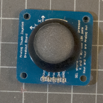
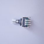
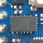
Figures 1-5 below are the parts you’ll need for this exercise. Click on any image for a larger view.


Connect the sensors
For this exercise, you’re going to need two analog inputs to your microcontroller, and one digital input. It doesn’t matter what they are, so use something that’s easy for you to set up. The photos and schematic in this lab show potentiometers and a pushbutton. You don’t have to use these, though. Any three sensor inputs will do the job. If you’re looking for options, consider:
As long as you have three sensors that will output changing readings, you can follow this lab.
Connect the two analog sensors to analog pins 0 and 1 like you did in the analog input to Arduino lab. Connect a pushbutton to digital pin 2 like you did in the digital input and output with Arduino lab.
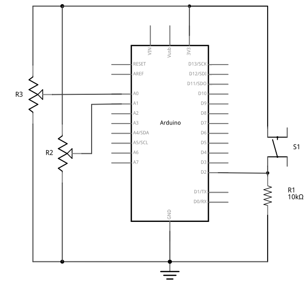
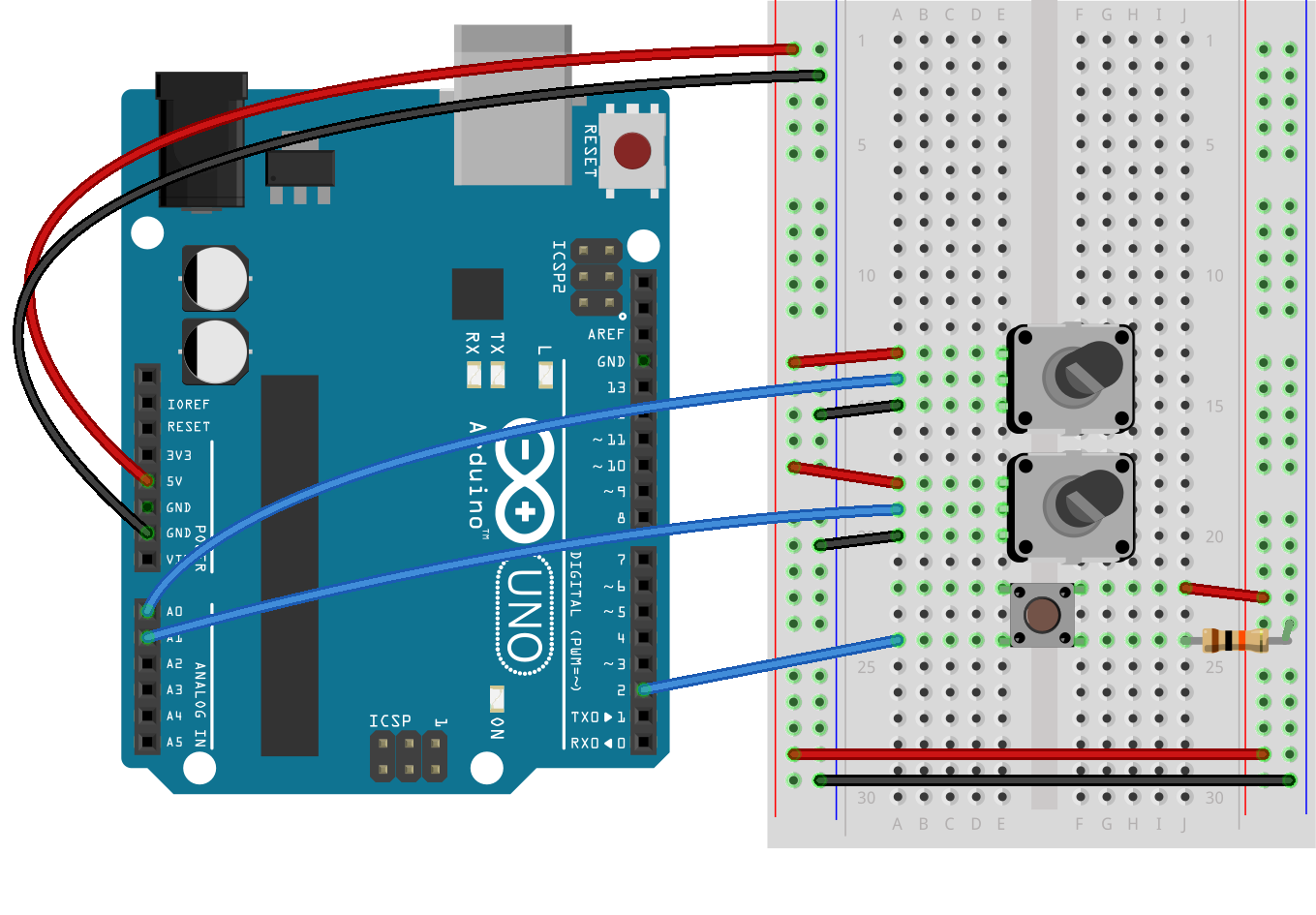
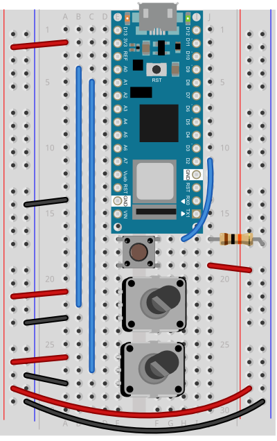
(Diagrams made with Fritzing, a circuit design program)
A Serial Output Sketch
To get started, upload the following sketch to your Arduino board, then open the Serial Monitor:
void setup() {
   // start serial port at 9600 bps:
   Serial.begin(9600);
}

void loop() {
   int analogValue = analogRead(A0);
   Serial.println(analogValue);
}
This will read the value from the first potentiometer, and print it to the Serial Monitor. You’ve already done this in the earlier labs. Now let’s get a deeper understanding of what’s going on between the Arduino and your personal computer.
Serial Terminal Programs
The Arduino Serial Monitor is a good basic way to see your serial communications, but it’s not the only way to view incoming serial data on your computer. There are many different serial terminal programs. Serial terminal programs allow you to send and receive messages from your computer’s serial ports. There are both graphical serial applications like CoolTerm or Serial Studio, and there are ways to read from the serial port from the command line terminal of your computer. For a beginner, the Arduino Serial Monitor does the job fine, but as you get more familiar with serial communication, you may want to get to know some of these. If you want to know about a few of them, read on. If not, feel free to skip to the next section on initializing serial communication.
Connecting via the POSIX Command Line
You can use a command line interface as a serial terminal program on MacOS or Linux, or Windows Subsystem for Linux (WSL). The simplest thing you can do with serial ports on the command line is to listen for incoming serial messages. Make sure your Arduino is running a sketch with at least one Serial.print() or Serial.println() statement in your code, like the one above.
- On MacOS, open the Terminal app, then get a list of your serial ports by typing
ls -1 /dev/cu.* - On Linux, you might need to type
ls -1 /dev/cu*orls -1 /dev/tty*instead. - On Windows, once you’ve installed WSL, open the Start Menu and type
wslto open a linux command line. Then when the command line window opens, typels -l /dev/tty* - You’ll get a list like this:
/dev/cu.Bluetooth-Incoming-Port

/dev/cu.lpss-serial2

/dev/cu.usbmodem14131
On Windows or Linux you’ll get a list like this:
/dev/tty
 /dev/ttyS0
 /dev/ttyS1
Each tty port in WSL corresponds to a COM port in Windows. So if your Arduino is showing up as COM7 to the Arduino IDE, then it’d be /dev/ttyS7 in wsl. It’s similar in Linux.
In MacOS, the Arduino is the one labeled usbmodemXXXX, as you’ve seen before in the Arduino IDE’s Serial Monitor. To see what the Arduino is sending out, type:
cat /dev/cu.usbmodem14131
in Windows and Linux, you’ll need to run the cat command as an admin user, so type:
sudo cat /dev/ttyS6
You’ll be prompted for your admin password. Enter it, then the command will run.
The terminal will then print out whatever the Arduino is sending. It’s using a POSIX command line application called cat, short for concatenate. This same application can be used for listing the contents of a file files, like so: cat filename.txt
To close the port and quit the cat application, type control-C. If you’ve got a continually repeating serial output, you may prefer to use the less command instead of cat. less /dev/cu.usbmodemXXXX will also print out the serial output, but it will stop after each screenful. Type the spacebar to page through multiple screens, or use the arrow keys to read up and down. Type q to exit.
Using the Command Line for Duplex (two-way) Communication
Another useful POSIX command line tool is the screen program. This allows you to both read from and write to a serial port. Type screen followed by the name of your serial port to open the interactive serial monitor called screen. Yours might look like this:
screen /dev/cu.usbmodem-1421
On Windows and Linux, remember to use sudo:
sudo screen /dev/ttyS6
The screen program will take your terminal over. You will be able to type messages to be sent out the serial port in addition to receiving them in the port. To end the screen program, type control-A control-D. This will quit the program.
NOTE: only one program can control a serial port at a time. When you’re not using a given program, remember to close the serial port. You won’t be able to re-program your Arduino module if you don’t, because the serial terminal program will have control of the serial port.
Sparkfun has a quick guide to other serial terminal connections from the command line on MacOS, Windows, and Linux as well.
GUI Serial Terminal Programs
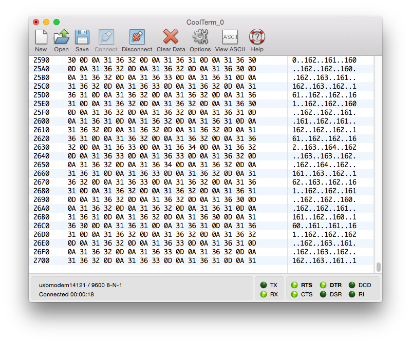
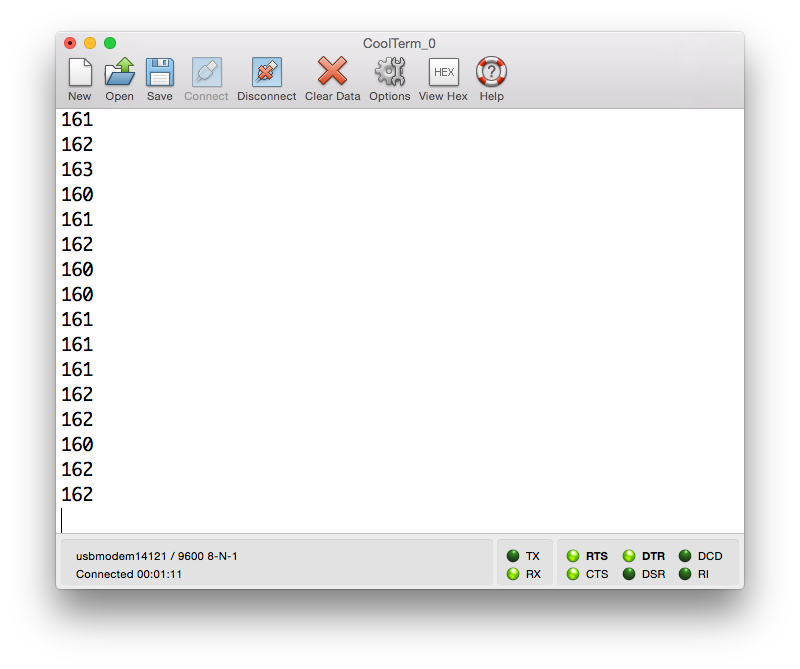
CoolTerm is a more fully-featured GUI serial terminal program. It’s free, it’s available for OSX, Windows and Linux, and includes some features you don’t get from the Serial Monitor, like being able to open multiple ports in multiple windows, being able to view your data in ASCII (Figure 10) or hexadecimal (Figure 9) values, and more.
Serial Studio is a fully-featured serial terminal program that allows you to configure dashboards to display data via JSON, send data over a network via MQTT or UDP, and many more features. It’s more than a beginner needs, but a useful advanced user’s tool.
The Serial Monitor, CoolTerm, Serial Studio and the screen program on the command line are all examples of a serial terminal program.
Related Video: Using the CoolTerm serial terminal application
Initializing Communication
What is asynchronous serial communication, anyway? Serial means that the two computers communicating are doing so one bit at a time, by sending pulses of data back and forth. Asynchronous means that the two computers that are communicating are each keeping track of time independently. As you know from the Asynchronous Serial Communications: the Basics page, there are three things the two computers need to agree upon:
- Electrical: what is the voltage of the pulses?
- Data rate: How often is a bit of data sent?
- Logic: Does low voltage mean the bit is a 0 or a 1?
Electrical and logic agreements are set for you when you use an Arduino. You set the data rate in your code. In your Arduino sketches so far, you’ve been setting the data rate to 9600 bits per second with this line:
Serial.begin(9600);
Whatever program you’re communicating to (whether it’s the Serial Monitor, CoolTerm, Serial Studio, the command line or another programming environment) has to set the same data rate. You can change both, as long as you change them to the same rate.
There are three connections between the two computers:
- a transmit line from sender to receiver
- a receive line from receiver to sender
- a common ground line
The transmit (sometimes called TX) and the receive (sometimes called RX) are relative: my transmit is connected to your receive, and vice versa. On the Arduino Uno and Nano 33 IoT, digital pins 0 and 1 are used for receive and transmit. They are attached to the USB-to-serial chip on the board. When you plug the Arduino into the computer, it shows up as a USB COM device, meaning a serial communications device. When you ask for a list of serial ports, whether in the Arduino Serial Monitor, CoolTerm, or any program, the Arduino will show up as a new port.
ASCII vs. Binary: What are you sending?
In order to communicate clearly between two devices, you need to understand how the devices are encoding the data which they’re communicating. There are two main approaches most computers use. They will either send the data directly, as a series of bits (this is called raw binary data), or they will encode the information as a series of alphanumeric characters (this is called ASCII-encoded data). This section explains the difference between ASCII and raw binary data.
To begin with, just send the value from one sensor, the first analog sensor (the first axis of the accelerometer in the photos) and divide the output to give a maximum value of 1023:
void setup() {
   // start serial port at 9600 bps:
   Serial.begin(9600);
}

void loop() {
   int analogValue = analogRead(A0);
   Serial.println(analogValue);
}
When you open the serial monitor, you should see a number between 0 and 1023 scrolling down the window. That’s because Serial.println() formats the value it prints as an ASCII-encoded decimal number, with a linefeed at a carriage return at the end. To send the value 1023, for example, println() sents six bytes: the characters 1, 0, 2, and 3, and a carriage return byte and a newline byte. Meanwhile, the serial monitor, receiving the data, assumes it should show you the ASCII character corresponding to each byte it receives.
The output from analogRead() can’t fit in a single byte, because the microcontroller’s analog-to-digital converter (ADC) reads the input with a resolution of 10 bits, or 210. To get the output into a single byte, map the output to a range from 0-255 like so:
void setup() {
   // start serial port at 9600 bps:
   Serial.begin(9600);
}

void loop() {
   int analogValue = analogRead(A0);
   int mappedValue = map(analogValue, 0, 1023, 0, 255);
   Serial.println(mappedValue);
}
Try it now, and your output should range from 0 to 255.
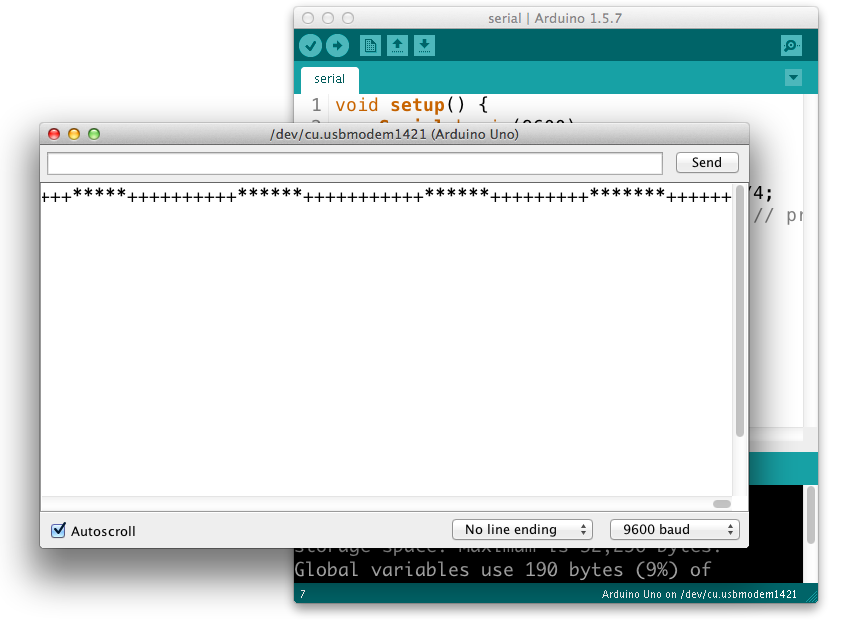
Try changing the Serial.println() to a Serial.write(). Now you get a range of garbage characters (Figure 11). What’s going on? The Serial.write() command doesn’t format the bytes as ASCII characters. It sends out the binary value of the sensor reading. Each sensor reading can range from 0 to 1023; in other words, it has a 10-bit range, since 210 = 1024 possible values. Since that’s more than the eight bits that can fit in a byte, you can either divide the value by 4 in the code above or use the map() function to get a range from 0 to 255, or 28 bits. For more background on this, see the notes on variables.
So, for example, if the sensor reading’s value is 234, then the Serial.write() command sends the binary value 11101010. If the reading is 255, then Serial.write() sends 11111111. If it’s 157, then the command sends 10011101. For more decimal-to-binary conversions, open your computer’s calculator and choose the Programmer view (press apple-3 on a mac, and Alt-3 on Windows). Sometimes you’ll see byte values in hexadecimal as well; for example, both CoolTerm and Serial Studio have hexadecimal modes. You can use the calculator to do these conversions too.
The garbage characters are characters corresponding to the ASCII values the Monitor is receiving. When the Serial Monitor receives a byte, it and assumes it should show you the ASCII character corresponding to that byte’s value.
For example, imagine that analogValue = 32:
Serial.println(analogValue)results in “32” with a linefeed and carriage returnSerial.write(analogValue)results in ” “, the space character, which has the ASCII value 32.
How many bytes does Serial.println(analogValue) send when analogValue = 32?
Serial.println( actually sends FOUR bytes! It sent a byte to represent the 3, a byte to represent the 2, a byte to tell the Monitor to move the cursor down a line (newline), and a byte to move the cursor all the way to the left (carriage return). The raw binary values of those four bytes are 51 (ASCII for “3”), 50 (ASCII for “2”), 10 (ASCII for “newline”), and 13 (ASCII for “carriage return”). Check the ASCII table and you’ll see for yourself.analogValue)
Send the data in many formats
Try this program and view the results in the Serial Monitor:
void setup() {
   // start serial port at 9600 bps:
   Serial.begin(9600);
}

void loop() {
// read analog input, map it to make the range 0-255:
int analogValue = analogRead(A0);
int mappedValue = map(analogValue, 0, 1023, 0, 255);
Serial.println(mappedValue);

// print different formats:
Serial.write(mappedValue);  // Print the raw binary value
Serial.print('\t');             // print a tab
// print ASCII-encoded values:
Serial.print(mappedValue, BIN); // print ASCII-encoded binary value
Serial.print('\t');             // print a tab
Serial.print(mappedValue);      // print decimal value
Serial.print('\t');             // print a tab
Serial.print(mappedValue, HEX); // print hexadecimal value
Serial.print('\t');             // print a tab
Serial.print(mappedValue, OCT); // print octal value
Serial.println();               // print linefeed and carriage return
}
You should get output like this:
â 11100010 226 E2 342
á 11100001 225 E1 341
á 11100001 225 E1 341
á 11100001 225 E1 341
à 11100000 224 E0 340
à 11100000 224 E0 340
ß 11011111 223 DF 337
ß 11011111 223 DF 337
ß 11011111 223 DF 337
This sketch is printing the raw binary value, then the ASCII-encoded binary value, then the ASCII-encoded decimal, hexadecimal, and octal values. You may never need all of these different formats, but you’ll likely need at least the decimal and the raw binary versions at some point.
What’s this \t, \r and \n Stuff, Anyway?
The ASCII table contains several characters that are “invisible”, like tab, newline, carriage return, and so forth. These characters tell the receiving program how to format the visible characters on the screen; newline tells the receiver to move down a line; carriage return tells it to move to the left edge of the screen, and so forth. In most programming languages, these characters are denoted with an escape string starting with a backslash: \. For example, newline is \n. Carriage return is \r. Tab is \t. When you see an escape string in a code sample, replace it with the appropriate ASCII value in your mind.
Send the values for all three sensors
In the first example above, using Serial.write(), you sent one byte representing one sensor’s value, over and over. When you’re sending multiple sensor values, it gets a little more complicated. You need to a way to know which value represents which sensor. For example, imagine if you sent the value of the potentiometers like so:
void loop() {
   int sensor1Value = analogRead(A0);
   Serial.print(sensor1Value);
   Serial.print(",");
   int sensor2Value = analogRead(A1);
   Serial.print(sensor2Value);
   Serial.print(",");
}
You’ll get a string like this:
452,345,416,234,534,417,325,452,231
How can you tell which value corresponds to which sensor? You don’t know which sensor is which. You could assume that if you start listening when the microcontroller starts sending that the first reading corresponds to the first sensor, but you can’t know that for sure. There are two ways to get your sensor values in order. You can use punctuation or you can use a call-and-response or handshaking method. Use whichever makes the most sense to you. They’re explained below.
Formatting Multiple Serial Data: Punctuation
One way to send the data such that it can be interpreted clearly is to punctuate each set of data uniquely. Just as a sentence ends with a period, you can end your data with a carriage return and a newline. Change the code above as shown below so that a carriage return and newline are printed at the end of each string of values.
void loop() {
   int sensor1Value = analogRead(A0);
   Serial.print(sensor1Value);
   Serial.print(",");
   int sensor2Value = analogRead(A1);
   Serial.println(sensor2Value);
}
From this loop, you’d get output like this:
452,345
234,534
325,452
This is much better. Whenever you get a newline, you know that the next value is the first sensor.
Now write a program that reads the two analog sensors on your board and the one digital switch, and prints them out in this format:
analog1, analog2, switch
analog1, analog2, switch
analog1, analog2, switch
Start by setting up a constant for the switch pin’s number. Then in the setup, initialize serial communications at 9600bps, and declare the switch pin as an input.
const int switchPin = 2;      // digital input

void setup() {
   // configure the serial connection:
   Serial.begin(9600);
   // configure the digital input:
   pinMode(switchPin, INPUT);
}
In the main loop, use a local variable called sensorValue to read each input. You can re-use the variable after each read because you don’t need the sensors’ values once you print them. Read the two analog inputs first, and print them with a comma after each one. Then read the digital input, and print it with a carriage return and linefeed at the end.
void loop() {
   // read the sensor:
   int sensorValue = analogRead(A0);
   // print the results:
   Serial.print(sensorValue);
   Serial.print(",");

   // read the sensor:
   sensorValue = analogRead(A1);
   // print the results:
   Serial.print(sensorValue);
   Serial.print(",");

   // read the sensor:
   sensorValue = digitalRead(switchPin);
   // print the results:
   Serial.println(sensorValue);
}
Once you’ve got a data format, all you have to do is to write a program that reads that format. You’ll see how do to that in this lab:
Flow Control: Call and Response (Handshaking)
Punctuation helps keep your data in order, but because asynchronous serial communication is asynchronous, you can run into a problem when the sender sends faster than the receiver can read. When this happens, the receiver program slows down as the serial buffer fills up. You can manage this by implementing some form of flow control. The simplest way do to this is using a call-and-response method, where the sending program only sends when it’s told to do so, and the receiving program has to request new data every time it finishes reading what it’s got.
You can add handshaking to the code above fairly simply. Modify the Arduino code as follows. First, add a a new block of code in the setup() This block sends out a message until it gets a byte of data from the remote computer:
void setup() {
   Serial.begin(9600);
   while (Serial.available() <= 0) {
     Serial.println("hello"); // send a starting message
     delay(300);              // wait 1/3 second
   }
}
Now, modify the loop() by adding an if() statement to look for incoming serial data and read it.
void loop() {
   if (Serial.available()) {
      // read the incoming byte:
      int inByte = Serial.read();
      // read the sensor:
      sensorValue = analogRead(A0);
      // print the results:
      Serial.print(sensorValue);
      Serial.print(",");

      // read the sensor:
      sensorValue = analogRead(A1);
      // print the results:
      Serial.print(sensorValue);
      Serial.print(",");

      // read the sensor:
      sensorValue = digitalRead(switchPin);
      // print the results:
      Serial.println(sensorValue);
   }
}
The rest of the sketch remains the same. When you run this and open the serial monitor, you’ll see:
hello
hello
hello
hello
Type any character in the output box and click Send. You’ll get a string of sensor values at the end of your hellos:
510,497,0
Type another character and click Send. It doesn’t matter what character you send, but the loop will always wait for an incoming byte before sending a new set of sensor values. When you write a program to receive this format, it just has to behave the same way you did:
Open the serial port
Wait for a Hello
Send a byte to request data
Begin loop:
  Wait for one set of data
  Send a byte to request new data
end loop
Advantages of Raw Binary vs. ASCII
All the examples shown here sent the sensor values as ASCII-encoded strings. As mentioned above, that means you sent three bytes to send a three-digit value. If that same value was less than 255, you could send it in one raw binary byte. So ASCII is definitely less efficient. However, it’s more readable for debugging purposes, and if the receiving program is well-suited to convert strings to numbers, then ASCII is a good way to go. For example, JavaScript sends data as ASCII strings almost by default, so it makes sense to use ASCII when writing in JavaScript. If the receiver’s not so good at converting strings to numbers (for example, it’s more challenging to read a multiple byte string in Arduino than in Processing) then you may want to send your data as binary values.
Advantages of Punctuation and Call-and-Response
The punctuation method for sending multiple serial values may seem simpler, but it has its limitations. You can’t easily use it to send binary values, because you need to have a byte with a unique value for the punctuation. In the example above, you’re using the value 10 (ASCII newline) as punctuation, so if you were sending your sensor values as raw bytes, you’d be in trouble when the sensor’s value is 10. The receiver would interpret the 10 as punctuation, not as a sensor value. In contrast, call-and-response can be used whether you’re sending data as raw binary values or as ASCII-encoded values.
Sometimes the receiver reads serial data slower than the sender sends it. For example, if you have a program that does a lot of graphic work, it may only read serial data every few milliseconds. For example, if you’re using P5.js, you may notice that using println() in the draw() loop will cause your sketch to slow down. The serial buffer will get full in that case, you’ll notice a lag in response time. This is when it’s good to switch to a call-and-response method.
Bonus Tip: writing Serial Data to a File
POSIX environments treat every input to the computer as a file stream, so when you’re using the cat command like you saw above, you’re telling the operating system to concatenate the serial input as if it’s a file. You can so some useful things as a result of this, like sending the serial output directly to a file.
Let’s say you want to save a few minutes of serial readings into a file. First, write a simple serial program that continually sends serial out, like you did earlier in this lab. Then, on the command line, type:
cat /dev/cu.usbmodem14131 > datalog.csv
You won’t see anything, unlike when you did it before, because now the cat program is redirecting to a file called datalog.csv, not to the command line. Type control-C to stop it, then open the file. You can do this from the Finder as you might usually, or you can just type
open datalog.csv
Since you made it a .csv file (for comma separated values), the operating system tries to open it with your spreadsheet program. This can be a quick way to get data into a structured format from your serial devices. For more on using the command line, see Karl Ward’s Introduction to Unix and the command line.
Further Work
The following labs will help you get better at serial communication: