Introduction
Inertial Motion Units (IMUs) are sensors that measure movement in multiple axes. Accelerometers measure a changing acceleration on the sensor. They can be used to measure the tilt of the sensor with respect of the Earth, or the force of a hit. They are common in mobile devices and automobiles. Gyrometers measure changing angular motion. They can be used to measure rotation. Magnetometers measure the magnetic force on a sensor. These are usually used to measure the Earth’s gravitational field in order to determine compass heading. IMUs have become increasingly common in microcontroller projects, to the point where they are built into some microcontroller boards like the Arduino 33 IoT and BLE Sense, and the Arduino 101. In this lesson, you’ll learn a few principles of working with these sensors, and see some examples.
What You’ll Need to Know
To get the most out of this lab, you should be familiar with the following concepts and you should install the Arduino IDE on your computer. You can check how to do so in the links below:
- What is a microcontroller
- Beginning programming terms
- The basics of electricity
- What is a solderless breadboard and how to use one
- Getting Started with Arduino Guide
- The basics of serial communication, both asynchronous and synchronous
Things You’ll Need
Figures 1-4 below show the parts you’ll need for this exercise. Click on any image for a larger view.


Orientation, Position, and Degrees of Freedom
“Orientation, or compass heading, is how you determine your direction if you’re level with the earth. If you’ve ever used an analog compass, you know how important it is to keep the compass level in order to get an accurate reading. If you’re not level, you need to know your tilt relative to the earth as well. In navigational terms, your tilt is called your attitude, and there are two major aspects to it: roll and pitch. Roll refers to how you’re tilted side-to-side. Pitch refers to how you’re tilted front-to-back.
“Pitch and roll are only two of six navigational terms used to refer to movement. Pitch, roll, and yaw refer to angular motion around the X, Y, and Z axes. These are called rotations. Surge, sway, and heave refer to linear motion along those same axes. These are called translations. These are often referred to as six degrees of freedom. Degrees of freedom refer to how many different parameters the sensor is tracking in order to determine your orientation.
“You’ll hear a number of different terms for these sensors. The combination of an accelerometer and gyrometer is sometimes referred to as an inertial measurement unit, or IMU… When an IMU is combined with a magnetometer, the combination is referred to as an attitude and heading reference system, or AHRS. Sometimes they’re also called magnetic, angular rate, and gravity, or MARG, sensors. You’ll also hear them referred to as 6-degree of freedom, or 6-DOF, sensors. There are also 9-DOF sensors that incorporate all three types of sensors. Each axis of measurement is another degree of freedom. [There are] even has 10-DOF sensor[s] that add barometric pressure sensor[s] for determining altitude.”
From Making Things Talk, 3rd edition
Features of an IMU
Whether you’re dealing with an accelerometer, gyrometer, or magentometer, there are a few features you’ll need to consider:
- Range – IMU sensors come in different ranges of sensitivity.
- Acceleration is generally measured in meters per second squared (m/s^2) or g’s, which are multiples of the acceleration due to gravity. 1g = 9.8 m/s^2. Accelerometers come in ranges from 2g to 250g and beyond. the force of gravity is 1g, but a human punch can be upwards of 100g
- Angular motion is measured in degrees per second (dps). Gyro ranges of 125dps to 2000 dps are not uncommon.
- Magnetic force is measured in Teslas. In most direction applications, the important measurement, however is the relative magnetic field strength on each axis.
- Number of axes – Almost all IMU sensors can sense their respective properties on multiple axes. Whatever activity you’re measuring, you’ll most likely want to know the acceleration, rotational speed, or magnetic force in horizontal and vertical directions. Most sensors give results for the X, Y, and Z axes. Z is typically perpendicular to the Earth, and the other two are parallel to it, but perpendicular to each other.
- Electrical Characteristics – as with any electronic sensor, you should pay attention to current consumption and make sure the rated voltage of your IMU is compatible with your microcontroller.
- Interface – IMUs come with a variety of interfaces. Some provide a changing analog voltage on each axis. Others will provide an I2C or SPI synchronous serial interface. Older IMUs will provide a changing pulse width that corresponds with the changing properties of the sensor. Nowadays, most IMUs are either I2C, SPI, or analog.
- Extra Features – in addition to the basic physical properties, many IMUs will have additional features, like freefall detection or tap detection, or additional control features like the ability to set the sensing rate.
For more on choosing an IMU, Sparkfun has an excellent introductory guide.
Most vendors of accelerometer modules do not actually make the sensors themselves, they just put them on a breakout board along with the reference circuit, for convenience. While you might buy your IMU from Sparkfun, Adafruit, Seeed Studio, or Pololu, for example, the chances are the actual sensor is manufactured by another company like Analog Devices, ST Microelectronics, or Bosch. When you shop for a sensor module, check out the manufacturer’s datasheet in addition to the vendor’s tech specs.
Analog IMUs
Analog IMU sensors typically have an output pin for each axis that outputs a range from 0 volts to the sensor’s maximum voltage. Most of them only have one form of sensor (accelerometer, gyrometer, magnetometer). Having multiple pins for each type of sensor would be unweildy.
Since it’s possible to have both positive and negative change in a given sensor’s range, the rest value for each output pin is usually in the middle of the voltage range. You need to understand this in order to read the sensor.
Analog Devices’ ADXL series of accelerometers are useful examples of this kind of sensor. There are two similar models, the ADXL335 and the ADXL377. The former is good for simple range of motion applications, and latter is designed for high-acceleration applications, like crashes, punches, and so forth. Both operate at 3.3V. Both output analog voltages for X, Y, and Z. Both output their midrange voltage, about 1.65V, on each axis when it’s at rest (at 0g). The ADXL335 is a +/-3g accelerometer, and the ADXL377 is a +/- 200g accelerometer. While you’d see a significant change on the ADXL335’s axes when you simply tilt the sensor, you’d see barely any when you simply tilt the ADXL377. Why? Consider the math:
The ADXL335 outputs 0V at -3g, 3.3V at +3g, and 1.65V at 0g. That means that 1g of acceleration changes the analog output by 1/6 of its range. If you’re using analogRead() on an Arduino with a 3.3V analog reference voltage, that means you’ve got a range of about 341 points per g of acceleration (1024 / 6). When you tilt the accelerometer to 90 degrees, you’re getting +1g on the X or Y axis. That’s a reading of about 682 using analogRead() on an Arduino. When you tilt it 90 degrees the other way, you’re getting -1g on the same axis, or about 341 using analogRead().
The ADXL377 outputs 0V at -200g, 3.3V at +200g, and 1.65V at 0g. That means 1g of acceleration changes the output by only 1/400 of its range. The same tilting action described above would give you a change from about 510 to 514 using analogRead(),using the same math as above.
This lesson applies whether you’re measuring acceleration, rotation, or magnetic field strength. Make sure to use a sensor that matches the required range otherwise you won’t see much change, particularly with an analog sensor.
Analog Accelerometer Example
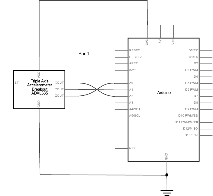
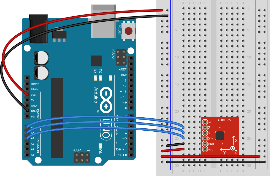
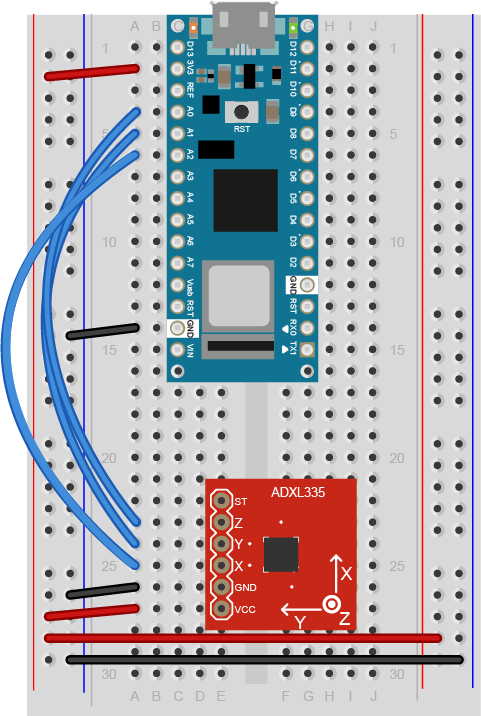
Figure 5 shows the schematic for connecting an ADXL335 to an Arduino, and Figures 6 and 7 show the breadboard view for the Uno and the Nano, respectively. For both boards, the accelerometer’s Vcc pin is connected to the voltage bus, and its ground pin is connected to the ground bus. The X axis pin is connected to the Uno’s analog in 2, the Y axis pin is connected to the Uno’s analog in 1, and the Z axis pin is connected to the Uno’s analog in 0.
Other analog IMUs are wired similarly.
The code below will read the accelerometer and print out the values of the three axes:
void setup() {
  Serial.begin(9600);
}

void loop() {
  int xAxis = analogRead(A2); // Xout pin of accelerometer
  Serial.print(xAxis);

  int yAxis = analogRead(A1); // Yout pin of accelerometer
  Serial.print(",");
  Serial.print(yAxis);

  int zAxis = analogRead(A0); // Zout pin of accelerometer
  Serial.print(",");
  Serial.println(zAxis);
}
Digital IMUs
Digital IMUs output a digital data stream via a serial interface, typically SPI or I2C. Unlike analog IMUs, these sensors can be configured digitally as well. Most support changing the sensitivity and the sampling rate, and some allow you to turn on and off features like tap detection or freefall detection.
Many digital IMUs are truly IMUs, in that they combine multiple sensors: accelerometer/gyrometer, accelerometer/gyrometer/magnetometer, and so forth.
Another advantage of digital IMUs is that they tend to convert their sensor readings at a higher level of resolution than a microcontroller’s analog input. While a microcontroller’s ADC is typically 10-bit (0-1023), many digital IMUs read their sensors into a 16-bit or even 32-bit result. This gives you greater sensitivity than an analog IMU.
Digital Accelerometer Example
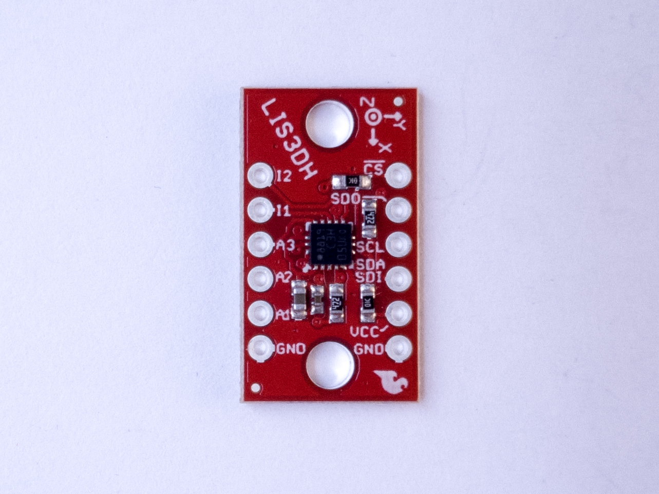
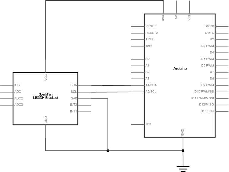
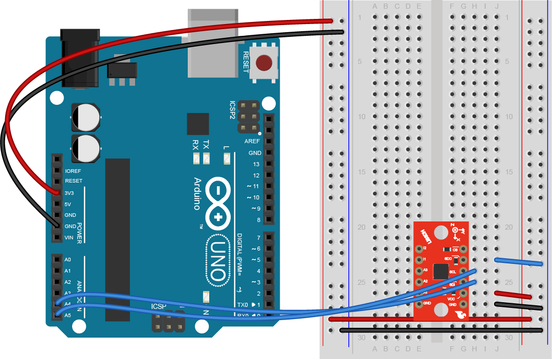
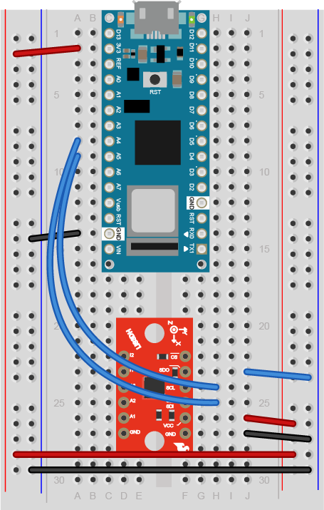
Figure 8 shows the schematic for connecting a LIS3DH accelerometer to an Arduino, and Figures 9 and 10 show the breadboard view for the Uno and the Nano, respectively. For both the Uno and the nano, the accelerometer’s Vcc pin is connected to the voltage bus, and its ground pin is connected to the ground bus. The SDA pin is connected to the microcontroller’s analog in 4, the SCL pin is connected to the microcontroller’s analog in 5 , and the SDO is connected to the ground bus. Other digital IMUs are wired similarly.
The following code will read the accelerometer and print out the acceleration on each axis in g’s. This accelerometer has a 14-bit range of sensitivity. The code below configures the accelerometer for a 2g range, and converts the 14-bit range to -2 to 2g. This is a simplification of one of the LIS3DH library examples by Kevin Townsend. It uses Adafruit’s LIS3DH library, but will work for any breakout board for the LIS3DH. It’s been tested with both Sparkfun’s and Adafruit’s boards for this sensor:
#include "Wire.h"
#include "Adafruit_LIS3DH.h"

Adafruit_LIS3DH accelerometer = Adafruit_LIS3DH();

void setup() {
  Serial.begin(9600);
  while (!Serial);
  if (! accelerometer.begin(0x18)) {
    Serial.println("Couldn't start accelerometer. Check wiring.");
    while (true);     // stop here and do nothing
  }
  accelerometer.setRange(LIS3DH_RANGE_8_G);   // 2, 4, 8 or 16 G
}

void loop() {
  accelerometer.read();      // get X, Y, and Z data
  // Then print out the raw data
  Serial.print(convertReading(accelerometer.x));
  Serial.print(",");
  Serial.print(convertReading(accelerometer.y));
  Serial.print(",");
  Serial.println(convertReading(accelerometer.z));
}

// convert reading to a floating point number in G's:
float convertReading(int reading) {
  float divisor = 2 <<; (13 - accelerometer.getRange());
  float result = (float)reading / divisor;
  return result;
}
Here’s a link to some more examples for the LIS3DH which work with either Adafruit’s or Sparkfun’s LIS3DH board.
Built-in IMUs
Some microcontroller boards, like the Nano 33 IoT and Nano 33 BLE sense and the 101, have built-in IMUs. These are digital IMUs, and they’re connected to either the SPI or I2C bus of the microcontroller. This means you might have conflicts if you’re using them along with an external I2C or SPI sensor. For example, when you’re using them as an I2C sensor, you need to know their I2C address so you don’t try to use another I2C sensor with the same address.
Most built-in IMUs will come with a board-specific library, like the 101’s CurieBLE or the Nano 33 IoT’s Arduino_LSM6DS3 library. Otherwise, they will be identical to the digital IMUs, so even with a built-in accelerometer, you can get more information from the accelerometer’s datasheet or the library’s header files.
Nano 33 IoT Built-In IMU Example
The LSM6DS3 IMU that’s on the Nano 33 IoT is an accelerometer/gyrometer combination. You can get both acceleration and rotation from it. The IMU is built into the board, so there is no additional circuit.
The code example below will read the accelerometer in g’s and the gyrometer in degrees per second and print them both out:
#include "Arduino_LSM6DS3.h"

void setup() {
  Serial.begin(9600);
  // start the IMU:
  if (!IMU.begin()) {
    Serial.println("Failed to initialize IMU");
    // stop here if you can't access the IMU:
    while (true);
  }
}

void loop() {
  // values for acceleration and rotation:
  float xAcc, yAcc, zAcc;
  float xGyro, yGyro, zGyro;

  // if both accelerometer and gyrometer are ready to be read:
  if (IMU.accelerationAvailable() &&
      IMU.gyroscopeAvailable()) {
    // read accelerometer and gyrometer:
    IMU.readAcceleration(xAcc, yAcc, zAcc);

    // print the results:
    IMU.readGyroscope(xGyro, yGyro, zGyro);
    Serial.print(xAcc);
    Serial.print(",");
    Serial.print(yAcc);
    Serial.print(",");
    Serial.print(zAcc);
    Serial.print(",");
    Serial.print(xGyro);
    Serial.print(",");
    Serial.print(yGyro);
    Serial.print(",");
    Serial.println(zGyro);
  }
}
What To Look For in an IMU Library
Different vendors will generally write their own libraries for the IMUs they sell. When you’re looking at a given vendor’s product, take a look at the properties of the sensor in the vendor’s datasheet, and the list of public functions in the library’s API. Does the library give you the functions of the sensor that you need? If the sensor supports multiple sensing ranges, does the library give you access to setting and getting the range? Is it well-documented, and well-commented? Are there simple, clear, well-commented examples?
For example, both Sparkfun and Adafruit make breakout boards for the LIS3SH accelerometer. This accelerometer is typical for a digital accelerometer; it’s got I2C and SPI interfaces, operates at 3.3V, and has a range of acceleration sensitivity, from 2g to 16g. The Adafruit getting started guide and the Sparkfun getting started guide get you up and running, but neither provides a summary of all the functions in their libraries. To see that, you need to look at the header files for each library. Adafruit’s header file is exhaustively commented, which can take time to get through. The key public functions start around line 344. It relies on their Unified Sensor library, which adds some complexity, but there are some nice additions, like the click functionality that the accelerometer supports. Sparkfun’s header file is less thoroughly commented, but shorter. The key public functions start about line 116. If you only need the basic acceleration functions, it’s easier to use because of less dependency on other libraries. Both are good libraries, though, and you should choose based on the features you want and how easy you find each to use.
You could use either library with either breakout board, but there is one catch: when you’re using the board’s I2C synchronous serial interface, you have to pay attention to the address you use in the the Adafruit board defaults to a different I2C address than the Sparkfun one. SparkFun defaults to 0x19, while Adafruit defaults to 0x18. In I2C mode, the SDO pin switches the I2C default address between 0x18 and 0x19. Taking this pin HIGH sets the address to 0x19, while taking it LOW sets it to 0x18, so by changing this pin, you can choose which library you prefer. Both libraries also have the ability to change the address they use for the accelerometer as well.
Determining Orientation
Determining orientation from an IMU takes some advanced math. Fortunately, there are a few algorithms for doing it. In 2010, Sebastian Madgwick developed and published a more efficient set of algorithms for determining yaw, pitch, and roll using the data from IMU sensors. Helena Bisby converted Madgwick’s algorithms into a Madgwick library for Arduino, improved upon by Paul Stoffregen and members of the Arduino staff. Though it was originally written for the Arduino 101, it can work with any IMU as long as you know the IMU’s sample rate and sensitivity ranges. Here’s an example that uses the Madgwick library and the Nano 33 IoT’s LSM6DS3 IMU to determine heading, pitch, and roll:
#include "Arduino_LSM6DS3.h"
#include "MadgwickAHRS.h"

// initialize a Madgwick filter:
Madgwick filter;
// sensor's sample rate is fixed at 104 Hz:
const float sensorRate = 104.00;

void setup() {
  Serial.begin(9600);
  // attempt to start the IMU:
  if (!IMU.begin()) {
    Serial.println("Failed to initialize IMU");
    // stop here if you can't access the IMU:
    while (true);
  }
  // start the filter to run at the sample rate:
  filter.begin(sensorRate);
}

void loop() {
  // values for acceleration and rotation:
  float xAcc, yAcc, zAcc;
  float xGyro, yGyro, zGyro;

  // values for orientation:
  float roll, pitch, heading;
  // check if the IMU is ready to read:
  if (IMU.accelerationAvailable() &&
      IMU.gyroscopeAvailable()) {
    // read accelerometer &and gyrometer:
    IMU.readAcceleration(xAcc, yAcc, zAcc);
    IMU.readGyroscope(xGyro, yGyro, zGyro);

    // update the filter, which computes orientation:
    filter.updateIMU(xGyro, yGyro, zGyro, xAcc, yAcc, zAcc);

    // print the heading, pitch and roll
    roll = filter.getRoll();
    pitch = filter.getPitch();
    heading = filter.getYaw();
    Serial.print("Orientation: ");
    Serial.print(heading);
    Serial.print(" ");
    Serial.print(pitch);
    Serial.print(" ");
    Serial.println(roll);
  }
}
Conclusion
There are dozens of accelerometers, gyrometers, and IMUs on the market, and as they become more ubiquitous in electronic devices, they continue to get smaller, cheaper, and more power-efficient. The principles laid out here should give you a basis for getting to know new ones as needed.