Lab: Setting Up A Breadboard

Introduction

The easiest way to get started building electronic circuits is by using a solderless breadboard. A breadboard is a tool for holding the components of your circuit, and connecting them together. It’s got holes that are the right size for hookup wires and the ends of most components, so you can push wires and components in and pull them out without much trouble. This lab shows how to set up a breadboard, both with an Arduino and with an independent power supply (9-12V) through a 5V Voltage Regulator (7805). By the time you finish the lab, you should have an understanding of how the holes in a solderless breadboard are connected, and how to configure your breadboard for different microcontroller projects, and even for projects without a microcontroller.

You won’t always need a voltage regulator. For most microcontroller circuits, you’ll get power from your computer’s USB port, regulated through your microcontroller, to power sensors and LEDs. But for higher current projects or higher voltage projects involving components like motors or larger light sources, it’s good to know what a voltage regulator is and how to use it.

Video: Connecting Power Supply to Breadboard with Regulator

If you’re using a brand new breadboard, you might want to check out these videos as well before you get started, to prep your board and care for your microcontroller.

What You’ll Need to Know

To get the most out of this lab, you should be familiar with the following concepts beforehand. If you’re not, review the links below:

  • What is a Voltage Regulator
  • Batteries and Power Supplies
  • All about DC Power supplies – this page will introduce you to DC power supplies. You probably have several in your house already, and this lesson will tell you more about how they work and how you can use them.

Safety Warning: When inserting components on or removing components from a breadboard always unplug power supply first! You are likely to damage your components if you are changing your circuit while it is still powered.

Things You’ll Need

A short solderless breadboard with two rows of holes along each side. There are no components mounted on the board.
Figure 1. A short solderless breadboard.
Three 22AWG solid core hookup wires. Each is about 6cm long. The top one is black; the middle one is red; the bottom one is blue. All three have stripped ends, approximately 4 to 5mm on each end.
Figure 2. 22AWG solid core hookup wires.
A DC power jack. It pairs with a plug with a 2.1mm inside diameter, 5.5mm outside diameter plug, and has screw terminals on the back so that you can attach wires to it.
Figure 4. A DC Power Jack
5-volt regulator, model 7805. This component has three legs and a tab at the top with a hole in it. If you hold the component with the tab at the top and the bulging side of the component facing you, the legs will be arranged, from left to right, voltage input, ground, and voltage output.
Figure 5. 5-volt voltage regulator, model 7805
Wire strippers. The jaws of this wire stripper have multiple hole sizes so that it can strip wires of variable sizes.
Figure 6. Wire stripper tool
Multimeter tool. This tool has a dial to set the function, and three holes into which to plug the testing leads. The leads are currently plugged into the center hole and the right hand hole.
Figure 7. Multimeter tool
LEDs. Shown here are four LEDs. The one on the right is an RGB LED. You can tell this because it has four legs, while the others have only two legs.
Figure 8. LEDs. Shown here are four LEDs. The one on the right is an RGB LED. You can tell this because it has four legs, while the others have only two legs.
Photo of an Arduino Nano 33 IoT module. The USB connector is at the top of the image, and the physical pins are numbered in a U-shape from top left to bottom left, then from bottom right to top right.
Figure 9. Arduino Nano 33 IoT. You could use any model of Arduino instead, for this lab.

Setting up the Breadboard

A solderless breadboard with a 7805 5-Volt voltage regulator mounted on it. There are several rows of holes for components. The holes on the breadboard are separated by 0.1-inch spaces, and are organized in many short rows in the center, and in two long rows down each side of the board. The short horizontal rows in the middle are separated by a center divider. The side rows are usually marked red, for voltage, and blue or black, for ground. On this breadboard, the side rows on the left side are connected to their counterparts on the right side with wires. The voltage regulator is mounted in the top three short rows on the right side of the board. The regulator faces to the left. The row holding the regulator's center pin is connected to the blue or black side row on the right side. The row holding the regulator's bottom pin is connected to the red side row on the right side.
Figure 10. Solderless breadboard with a 7805 voltage regulator mounted on it.

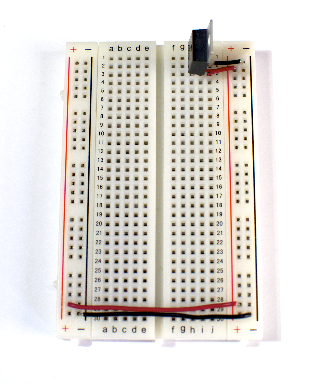
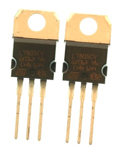
Figure 10 shows a typical breadboard with a 7805 5-Volt voltage regulator mounted on it. There are several rows of holes for components. The holes on the breadboard are separated by 0.1-inch spaces, and are organized in many short rows in the center, and in two long rows down each side of the board. The short horizontal rows in the middle are separated by a center divider. The pattern varies from model to model; some breadboards have only one strip down each side, others have multiple side rows, and some have no side rows at all.

Related Video: Introduction to breadboards

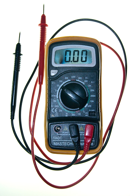
On each side of the board are two long rows of holes, with a black or a red line next to each row (on many boards, you’ll see a blue row instead of black).  All the holes in each of these lines are connected together with a strip of metal in the back. In the center are several short rows of holes separated by a central divider. All of the five holes in each row in the center are connected with a metal strip as well. This allows you to use the holes in any given row to connect components together. To see which holes are connected to which, take a multimeter and a couple of wires, set the multimeter to measure continuity, stick the two wires in two holes, and measure them with the multimeter. If the meter indicates continuity, then the two holes in question are connected.

What’s Inside A Breadboard?

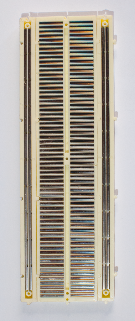
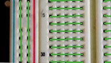
The image below (Figure 11) of the back of a breadboard may help to clear up how the holes on the front of the board are connected. The backing of the board has been removed (don’t remove the backing on your own board! It will make the board useless) to expose the metal strips connecting the holes. You can clearly see the short horizontal strips in the center separated by the divider, and the long strips vertically down the side. The detailed photo in Figure 12  illustrates how the holes and strips are related. Each of the holes connected to the horizontal strips are connected, and each of the holes connected to each long vertical side strips are connected to each other.

The back of a breadboard with the adhesive backing removed, showing the metal strips underneath. Each long row down the side has a continuous metal strip underneath, running vertically down the board. The metal strip connects all the holes in its row. The holes of the short rows are connected with short metal strips running perpendicular to the long strips on the side. There is a break in the middle of the board, so that there is no connection between the right side and the left side.
Figure 11. The back of a breadboard, shown with the backing removed.
A close-up picture of the front of the breadboard. The green lines indicate which holes are connected by a metal strip behind. Each short horizontal group of five holes is connected, and each long vertical group of holes is connected. The vertical groups are not connected to each other or to the horizontal groups, however.
Figure 12. A close-up picture of the front of the breadboard. The green lines indicate which holes are connected by a metal strip behind.

The reason for the center divider is so that you can mount integrated circuit chips, like a microprocessor, on the breadboard. IC chips in a DIP package (Dual In-line Package) have two rows of pins that to which you need to connect other components. The center row isolates the two rows from each other, and gives you several holes connected to each pin, so that you can connect other components.

Powering the Breadboard

Avoid adding, removing, or changing components on a breadboard whenever the board is powered. You risk shocking yourself and damaging your components.

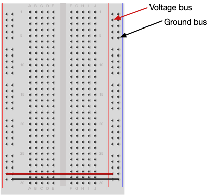
The most common connections you need on a breadboard are voltage and ground. That’s why solderless breadboards are designed the way they are. The long rows of connected holes down either side are designed to be used as power and ground buses. A bus is a long electrical connection that has many points where you can connect to it. Figure 13 shows the typical wiring on a breadboard, connecting the bus rows on the left with those on the right.

A solderless breadboard with the voltage and ground buses indicated on the sides.
Figure 13. A solderless breadboard with the voltage and ground buses indicated on the sides. The left and right sides of the board are connected via two wires which connect the voltage bus on the left with the one on the right, and the ground bus on the left with the one on the right.

Next you’ll see how to connect an Arduino microcontroller to your breadboard to supply power to the components on the board. Later on, you’ll see how to power a board without a microcontroller.

Using a Breadboard with a Microcontroller

For most projects in this class you’ll power your circuit via a microcontroller like the Arduino Nano 33 IoT or the Uno. To do that, your breadboard will usually be connected as shown in Figures 14 and 15. You’ll connect the voltage and ground buses on the breadboard to voltage and ground from the microcontroller. On the Arduino module, you can use the 5V or 3.3V output, depending on the circuit you are using and depending on your model. Typically, you’ll use 5V on the Uno and 3.3V on the Nano 33 IoT.

An Arduino Uno on the left connected to a solderless breadboard, right. The Uno's 5V output hole is connected to the red column of holes on the far left side of the breadboard. The Uno's ground hole is connected to the blue column on the left of the board. The red and blue columns on the left of the breadboard are connected to the red and blue columns on the right side of the breadboard with red and black wires, respectively. These columns on the side of a breadboard are commonly called the buses. The red line is the voltage bus, and the black or blue line is the ground bus.
Figure 14. Breadboard view of an Arduino Uno on the left connected to a solderless breadboard, right.

As shown in Figure 15, the Uno’s 5V output hole is connected to the red side column of holes on the far left side of the breadboard; this is the voltage bus. The Uno’s ground hole is connected to the blue side column on the left of the board, or ground bus. The red and blue columns on the left of the breadboard are connected to the red and blue columns on the right side of the breadboard with red and black wires, respectively. With this setup, you can supply 5V to any component on the breadboard, using the Uno’s onboard 5-volt regulator. You can power the Uno either through USB or through a 9-12V power supply plugged into the Uno’s power jack. There is a limit to the current that you can supply from this regulator, though, about 1 amp at 5V.

If you’re using an Uno for this lab, connecting the circuit in Figure 14, then set your multimeter to measure DC voltage, and measure the voltage between the voltage and ground buses of your breadboard. When the Uno is plugged into a USB power supply, you should get 5V.


Arduino Nano on a breadboard.
Figure 15. Breadboard view of an Arduino Nano mounted on a solderless breadboard.

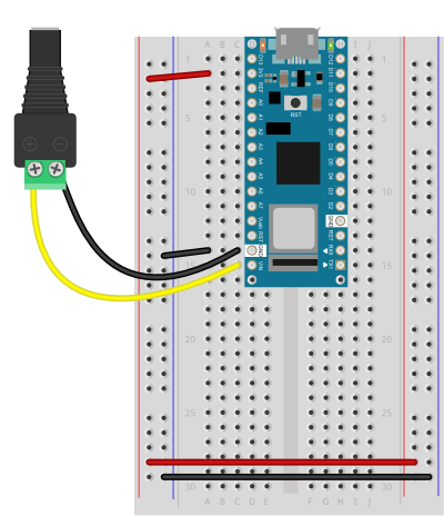
In Figure 15, you see a similar setup for the Arduino Nano 33 IoT. The Nano is mounted at the top of the breadboard, straddling the center divide, with its USB connector facing up. The top pins of the Nano are in row 1 of the breadboard.

The Nano, like all Dual-Inline Package (DIP) modules, has its physical pins numbered in a U shape, from top left to bottom left, to bottom right to top right. The Nano’s 3.3V out pin (physical pin 2) is connected to the left side red column of the breadboard. This is the voltage bus. The Nano’s GND pin (physical pin 14) is connected to the left side black column, the ground bus. The blue columns (ground buses) are connected together at the bottom of the breadboard with a black wire. The red columns (voltage buses) are connected together at the bottom of the breadboard with a red wire. Wired like this, you can supply 3.3V to any component on the breadboard through the Nano’s onboard 3.3V regulator. There is a limit to the current that you can supply from this regulator, though, about 1 amp at 3.3V.

If you’re using a Nano for this lab, connecting the circuit in Figure 15, then set your multimeter to measure DC voltage, and measure the voltage between pin 2 of the Nano (3.3V out) and pin 14 (ground). When the Nano is plugged into a USB power supply, you should get 3.3V.

Powering A Breadboard Circuit From A Microcontroller Via A DC Power Supply

Quite often, you’ll want to supply power to a circuit through an Arduino. Sometimes, you’ll have components that run at the microcontroller’s voltage, and sometimes they will require a higher voltage. From both the Nano and the Uno, if you power them from a DC power supply, you can supply 5V, 3.3V and the voltage of the power supply.

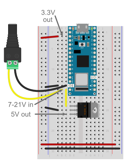
When you’re not powering it via its USB connector, the Nano 33 IoT and the Nano Every can be powered through the Vin pin (pin 15, bottom left side of the module) by a voltage range from 7 – 21 volts. This wide range means that you can use a 9V battery, or a DC power supply anywhere from 7-21V. When you power the Nano this way, you get 3.3V from the 3V3 pin (pin 2) just as if you were powering from USB. If you have components that need a higher voltage, you can supply them directly from your power supply via the Vin pin. Figure 16 shows a Nano powered from a 12V DC power jack. The Jack’s positive terminal is connected to the Vin pin (pin 15) and the negative terminal is connected to the ground pin (pin 14).

 Breadboard view of a Nano 33 IoT on a breadboard connected to a DC power jack for external DC powering.
Figure 16. Breadboard view of a Nano 33 IoT on a breadboard connected to a DC power jack for external DC powering. The jack’s positive terminal is connected to the Nano’s Vin pin (pin 15) and the negative terminal is connected to ground (pin 14). In this configuration, the Nano will run, and will output 3.3V between the 3V3 pin (pin 2) and ground.

When you are using a DC power supply as shown in Figure 16, you can also add a 5V regulator powered by the power supply, if you need both 3.3V and 5V for your components. Figure 17 shows a Nano supplied by a DC power jack on the Vin and ground pins, and a 5V regulator attached to the Vin pin as well, to supply 5V for components that need that voltage.

Try connecting the circuit in Figure 17, then set your multimeter to measure DC voltage, and measure the voltage between pin 2 of the Nano (3.3V out) and pin 14 (ground). When the DC power jack is plugged in, you should get 3.3V. Now move the positive (red) probe of your meter to the bottom pin of the voltage regulator (row 21 on the board). You should read 5V. Now move the positive probe to the Nano’s pin 16 (Vin). You should read whatever the voltage of the DC power supply is, somewhere between 7 and 21V.

Breadboard view of a Nano 33 IoT and a 7805 voltage regulator powered from a DC power jack.
Figure 17. Breadboard view of a Nano 33 IoT and a 7805 voltage regulator powered from a DC power jack. The DC power jack is wired as shown in the previous figure (positive terminal to Vin, negative terminal to ground. However, in this image, a 5V regulator is added on the breadboard below the Nano. Its Vin pin is connected to the Vin of the Nano (and the DC power supply’s positive terminal) and its ground is connected to the ground bus. In this circuit, you can supply 3.3V via the Nano’s 3V3 pin (pin 2), 5V from the 7805 regulator, and 7-21V from the DC power supply.

The Uno accepts 7-12V in via its DC power jack, and it has two voltage regulators on board. Pin 5 on the left side of the board supplies 5V, and pin 4 on the left side supplies 3.3V. Pin 8 on the left side is connected directly to the Vin, so you can supply 7-12V, depending on the voltage of your DC power supply, from that pin. For example, figure 18 shows an Uno connected to a 9V battery and supplying 9V to the breadboard via the Vin pin.

Uno connected to a 9V battery via a battery clip.
Figure 18. Uno connected to a 9V battery via a battery clip. The Uno’s Vin pin (pin 8 on the left side) is connected to a breadboard’s voltage bus, and one of the ground pins (pin 7) is connected to the ground bus. The Uno is thus supplying 9V for any components on that breadboard.

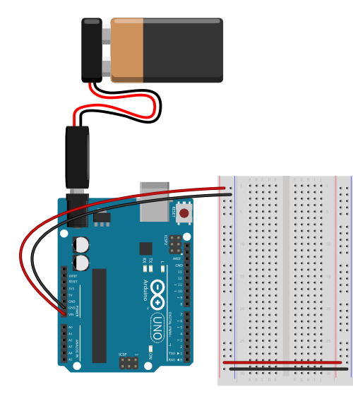
If you’re using an Uno for this lab, connecting the circuit in Figure 18, then set your multimeter to measure DC voltage, and measure the voltage between the voltage and ground buses of your breadboard. When the Uno is plugged into a DC power supply, you should get whatever the voltage of the DC power supply is, between 7 and 12V.

With an external power supply and a voltage regulator, you can supply almost any voltage your components might need, while still giving the Arduino the voltage it needs to run. In general, you will always connect the ground lines together, and keep the different voltages separate from each other. To see an application of this, see the Using a Transistor to Control High Current Loads with an Arduino Lab.

You can use the circuits above as templates for almost any microcontroller-driven project. Even if you’re just using the microcontroller to power the breadboard, as shown below, you can still work with these circuits as a base.

Powering the Breadboard without a Microcontroller

Close-up showing a 7805 5-volt voltage regulator connected to a breadboard. The breadboard is oriented so that the long rows are horizontal this time, and you are looking at the back of the regulator. The regulator is connected to the right-most three rows of the board.
Figure 19. Close-up showing a 7805 5-volt voltage regulator connected to a breadboard.

Sometimes you’ll want to build circuits without a microcontroller. This section shows you how to set up a breadboard without a microcontroller. You’ll add a 5-volt voltage regulator, and power the board from a 12-volt DC power adapter which feeds the regulator.

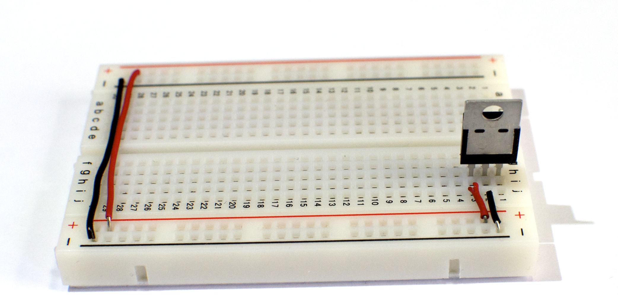
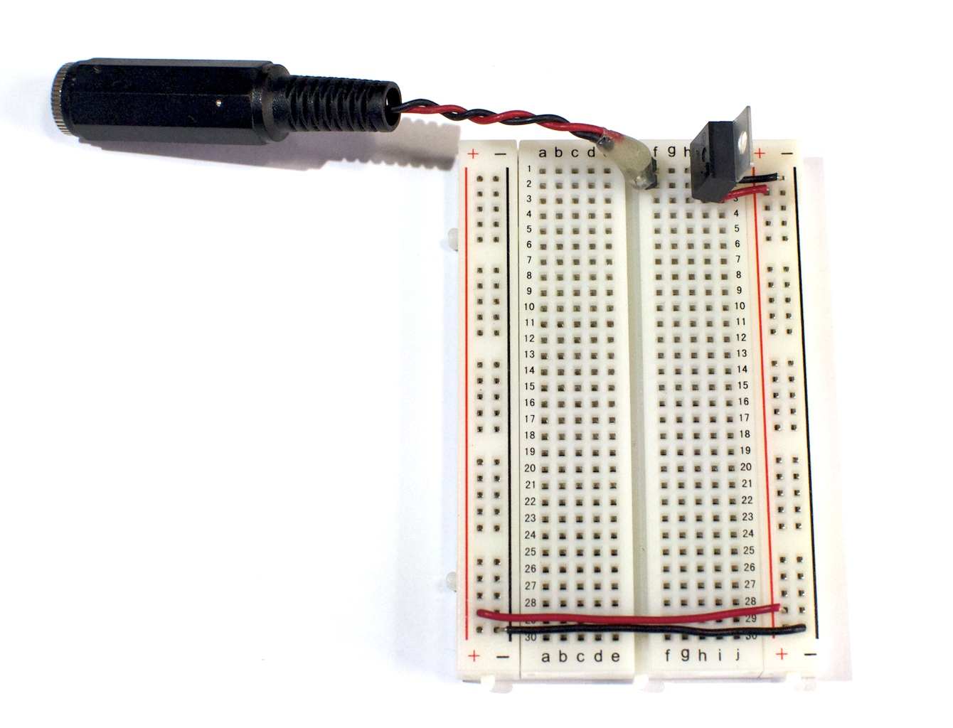
The regulator in Figure 19 is used to supply 5 Volts to the red side columns of the breadboard. In this image, you’re looking at the board sideways, with the the back of the regulator facing you. The pins of the regulator are, from left to right: voltage out, ground, voltage in. Notice that the regulator’s voltage out pin on the left is connected to the red side row of the breadboard with a red wire. The regulator’s center pin (ground) is connected to the black side row. These will be your voltage and ground bus rows. The side rows on one side are connected to the corresponding side rows on the other side via two wires. The two black rows are connected to each other via a black wire, and the red rows are connected via a red wire.

Related Video: Using a voltage regulator on a breadboard

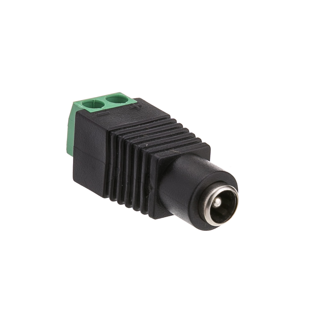
With your board connected like this, you’ll be able to build many different 5-Volt circuits on the board. The last thing you need to add is a power connector to connect 9 – 12 volts DC to supply power for the voltage regulator. Figure 20 below shows a power connector connected to the voltage input and ground pins of the voltage regulator. This circuit is now the same as the one shown in Figure 17 above, but with the Arduino Nano removed.

Related Video: Wiring a power supply using a DC power jack

breadboard_power_jack
Figure 20. Board with 5V voltage regulator and power connector ready to go.

Will it Light? Test Your Understanding

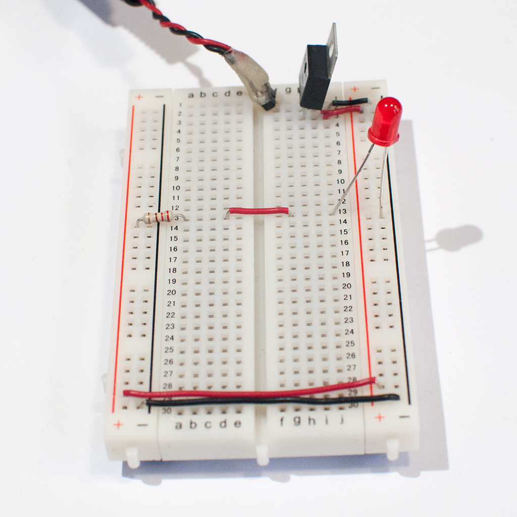
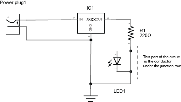
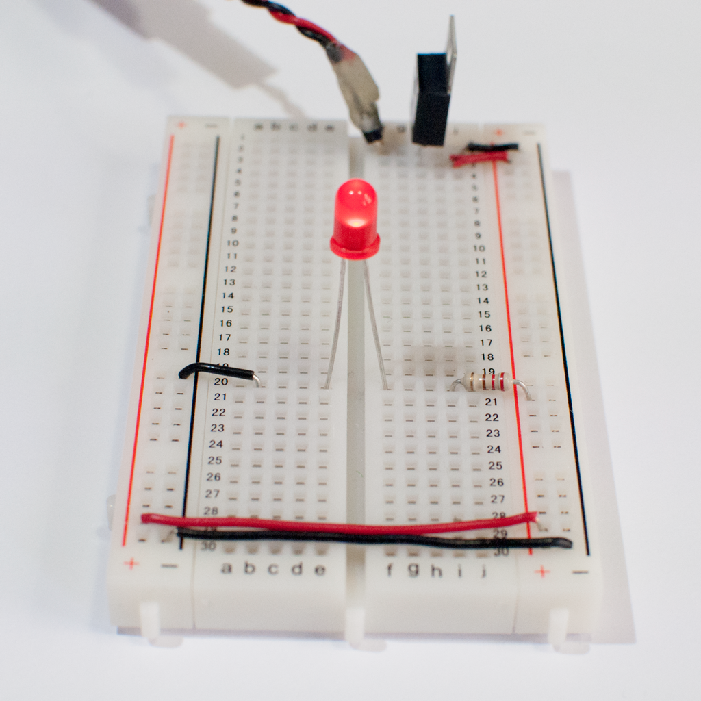
Figures 22-30 below show an LED and a resistor connected in a breadboard. Some are connected correctly and others are not. Take a guess as to whether the LED will light or not, then click the links below the image to find out. All of the circuits below are versions of the same circuit, shown in the schematic in Figure 21:

Schematic image of a 220-ohm resistor and an LED connected to a 7805 5-volt regulator. At left, there is a power plug. The positive terminal of the power plug is connected to the voltage input of a 7805 voltage regulator. The negative terminal of the power plug is connected to the ground terminal of the regulator. The voltage output of the regulator is connected to a 220-ohm resistor. The other side of the resistor is connected to the anode of an LED. The cathode of the LED is connected to the ground terminal of the regulator.
Figure 21. Schematic image of a 220-ohm resistor and an LED connected to a 7805 5-volt regulator. Regulator pins are numbered from left to right.  One terminal of the resistor is connected to the regulator’s output pin (pin 3), and the other terminal is connected tothe LED’s anode. The LED’s cathode is attached to the regulator’s ground pin (pin 2). A 9-12V DC power source is connected to the regulator’s voltage in (pin 1) and ground (pin 2). Download the tactile schematic as SVG. Download the tactile schematic key as SVG.

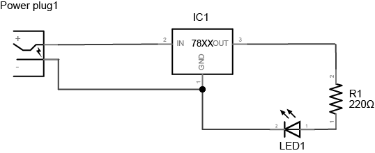
These circuit images will test your understanding of how the breadboard works. You can build the circuits yourself, using any one of Figures 14, 15, 17 or 20 to supply 5V for the LED circuit.

If your board is wired as in Figure 22, will the LED below light up when you power the board? Take a guess, then click the link below the image to find out.

Photo of a solderless breadboard with a 7805 voltage regulator mounted on it, as in the images above. The regulator is connected to a DC power plug, and the ground and voltage output of the regulator is connected to the voltage and ground bus rows on the right side of the breadboard. The ground and voltage bus rows on the right are connected to the ground and voltage bus rows on the left with wires at the bottom of the board. A 220-ohm resistor is connected to the voltage bus on the left. Its other end is connected to row twelve in the center area. An LED is connected to another hole in row twelve. The other side of the LED is connected to a hole in row fourteen. Another hole in row fourteen connects to the ground bus on the right side of the board.
Figure 22. Photo of a solderless breadboard with a 7805 voltage regulator mounted on it, as in the images above. The regulator is connected to a DC power plug, and the ground and voltage output of the regulator is connected to the voltage and ground bus rows on the right side of the breadboard. The ground and voltage bus rows on the right are connected to the ground and voltage bus rows on the left with wires at the bottom of the board. A 220-ohm resistor is connected to the voltage bus on the left. Its other end is connected to row twelve in the center area. An LED is connected to another hole in row twelve. The other side of the LED is connected to a hole in row fourteen. Another hole in row fourteen connects to the ground bus on the right side of the board.

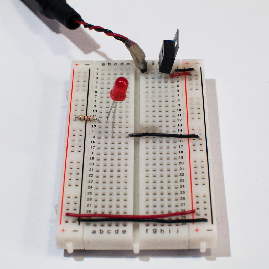
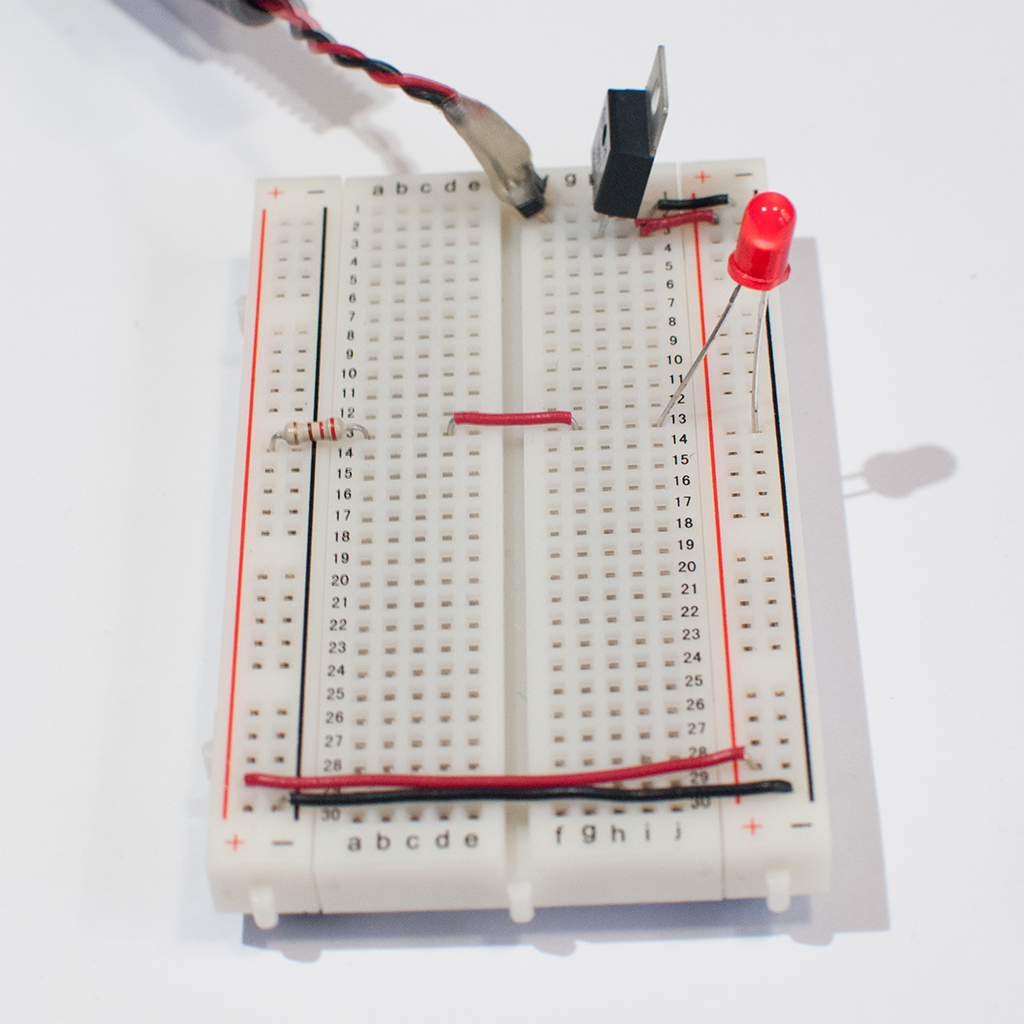
Try another one. When wired as in Figure 24, will the LED below light up when you power the board? Take a guess, then click the link below the image to find out.

Photo of a solderless breadboard with a 7805 voltage regulator mounted on it, as in the images above. The regulator is connected to a DC power plug, and the ground and voltage output of the regulator is connected to the voltage and ground bus rows on the right side of the breadboard. The ground and voltage bus rows on the right are connected to the ground and voltage bus rows on the left with wires at the bottom of the board. A 220-ohm resistor is connected to the voltage bus on the left. Its other end is connected to row twelve in the center area. An LED is connected to a hole in row twelve on the right side. The other side of the LED is connected the ground bus on the right side.
Figure 24. Photo of a solderless breadboard with a 7805 voltage regulator mounted on it, as in the images above. The regulator is connected to a DC power plug, and the ground and voltage output of the regulator is connected to the voltage and ground bus rows on the right side of the breadboard. The ground and voltage bus rows on the right are connected to the ground and voltage bus rows on the left with wires at the bottom of the board. A 220-ohm resistor is connected to the voltage bus on the left. Its other end is connected to row twelve in the center area. An LED’s anode is connected to a hole in row twelve on the right side. The cathode of the LED is connected the ground bus on the right side.

Here’s a third one, Figure 25. Will the LED below light up when you power the board? Take a guess, then click the link below the image to find out.

Photo of a solderless breadboard with a 7805 voltage regulator mounted on it, as in the images above. The regulator is connected to a DC power plug, and the ground and voltage output of the regulator is connected to the voltage and ground bus rows on the right side of the breadboard. The ground and voltage bus rows on the right are connected to the ground and voltage bus rows on the left with wires at the bottom of the board. A 220-ohm resistor is connected to the voltage bus on the left. Its other end is connected to row thirteen in the center area. A red wire connects row thirteen on the left with row thirteen on the right. An LED is connected to a hole in row thirteen on the right side. The other side of the LED is connected the ground bus on the right side.
Figure 25. Photo of a solderless breadboard with a 7805 voltage regulator mounted on it, as in the images above. The regulator is connected to a DC power plug, and the ground and voltage output of the regulator is connected to the voltage and ground bus rows on the right side of the breadboard. The ground and voltage bus rows on the right are connected to the ground and voltage bus rows on the left with wires at the bottom of the board. A 220-ohm resistor is connected to the voltage bus on the left. Its other end is connected to row thirteen in the center area. A red wire connects row thirteen on the left with row thirteen on the right. An LED’s anode is connected to a hole in row thirteen on the right side. The cathode of the LED is connected the ground bus on the right side.

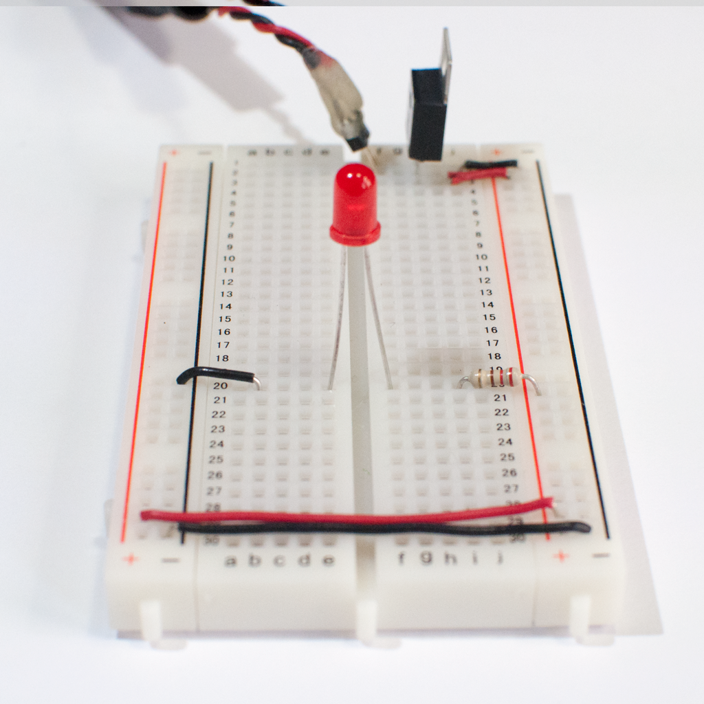
Here’s another test. In Figure 27, will the LED below light up when you power the board? Take a guess, then click the link below the image to find out.

Photo of a solderless breadboard with a 7805 voltage regulator mounted on it, as in the images above. The regulator is connected to a DC power plug, and the ground and voltage output of the regulator is connected to the voltage and ground bus rows on the right side of the breadboard. The ground and voltage bus rows on the right are connected to the ground and voltage bus rows on the left with wires at the bottom of the board. A 220-ohm resistor is connected to the voltage bus on the left. Its other end is connected to row fifteen in the center area. An LED is connected to two holes in row fifteen of the left side of the board as well. A black wire connects row fifteen on the left side of the board to the ground bus on the right side of the board.
Figure 27. Photo of a solderless breadboard with a 7805 voltage regulator mounted on it, as in the images above. The regulator is connected to a DC power plug, and the ground and voltage output of the regulator is connected to the voltage and ground bus rows on the right side of the breadboard. The ground and voltage bus rows on the right are connected to the ground and voltage bus rows on the left with wires at the bottom of the board. A 220-ohm resistor is connected to the voltage bus on the left. Its other end is connected to row fifteen in the center area. An LED is connected to two holes in row fifteen of the left side of the board as well. A black wire connects row fifteen on the left side of the board to the ground bus on the right side of the board.

Here’s a final test. In Figure 29, will the LED below light up when you power the board? Take a guess, then click the link below the image to find out.

Photo of a solderless breadboard with a 7805 voltage regulator mounted on it, as in the images above. The regulator is connected to a DC power plug, and the ground and voltage output of the regulator is connected to the voltage and ground bus rows on the right side of the breadboard. The ground and voltage bus rows on the right are connected to the ground and voltage bus rows on the left with wires at the bottom of the board. A 220-ohm resistor is connected to the voltage bus on the right. Its other end is connected to row twenty in the on the right side of the center area. An LED is connected to a hole in row twenty on the right side as well. The other side of the LED is connected row twenty on the left side. A black wire connects row twenty on the left with the ground bus on the left side.
Figure 29. Photo of a solderless breadboard with a 7805 voltage regulator mounted on it, as in the images above. The regulator is connected to a DC power plug, and the ground and voltage output of the regulator is connected to the voltage and ground bus rows on the right side of the breadboard. The ground and voltage bus rows on the right are connected to the ground and voltage bus rows on the left with wires at the bottom of the board. A 220-ohm resistor is connected to the voltage bus on the right. Its other end is connected to row twenty in the on the right side of the center area. An LED is connected to a hole in row twenty on the right side as well. The other side of the LED is connected row twenty on the left side. A black wire connects row twenty on the left with the ground bus on the left side.

Below, in Figure 31, the three LED’s are connected in parallel using two rows. They are then connected to power and ground by connecting the rows to the voltage row and the ground row. These three LEDs are in parallel with each other.

Three LEDs mounted on a solderless breadboard. The three LEDs in this photo are connected in parallel using two rows. All of their anodes are connected to row 37 on the left side of the center area. All of their cathodes are connected to row 40 on the left side. They are then connected to voltage and ground through wires connecting the rows to the voltage row and the ground rows on the left side of the board.
Figure 31. LEDS in parallel on a breadboard

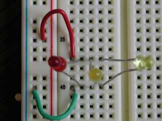
Many options are possible using a breadboard, which is what makes them very useful and convenient for building circuits. Once you understand which holes are connected to each other (and which ones are not), you can build any circuit very quickly.

Breadboarding Best Practices

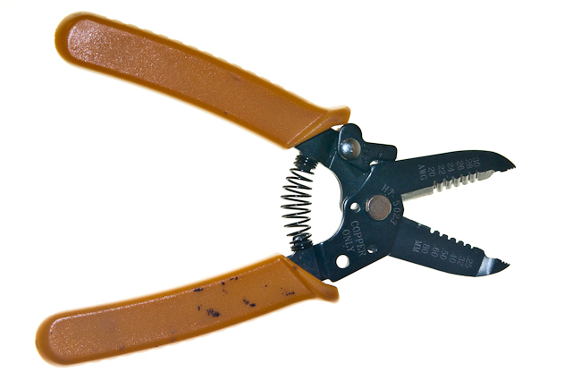
It’s a good idea to keep your circuits neat. When possible, shorten the leads on components so there is no bare metal sticking up from the breadboard. Make sure no wires cross each other with metal touching (this is the biggest source of short circuits on a breadboard). Lay things out as sensibly as possible, so each component of the circuit is near the components it needs to connect to. Use wires when needed to separate parts of the circuit that are crowded together. Use consistent colors of wires when possible; for example, use green or black for ground connections, red for power connections, white or blue for data connections, and so forth. This will make your troubleshooting much easier.