Overview
Power supply is a reference to the source of electrical power. Most electronic circuits require a DC power supply. Chances are you have one at home already, and can use it for physical computing projects.
The most common operating voltages for microcontrollers and digital processors are 5V and 3.3V. You can find power supplies in many voltages, but 5V and 12V are common. To convert 12V to 5V or 3.3V, you’d need a voltage regulator. The Breadboard Lab covers how to set that up.
There are many different kinds of DC power supplies but this one shown in Figure 1 is most commonly used at ITP:
– Click on any image for a larger view
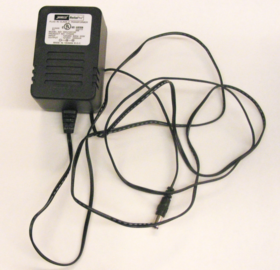
Jameco 12V Regulated Switching Power Supply
Part# 170245 (12V, 1000mA)
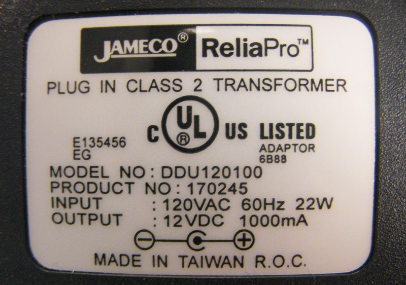
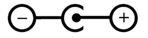
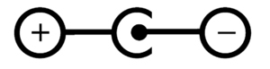
Most power supplies have a rating label that looks something like the one in Figure 2. Make sure you know the polarity of the plug so you don’t reverse polarity for your circuit and damage your components. The diagram in Figure 3 and Figure 4 showing positive tip polarity is on the left and negative tip polarity is on the right. The center positive drawing on the left indicates that the center (tip) of the output plug is positive (+) and the barrel of the output plug is negative (-).
,
Abbreviations
V : Volts
A : Amperes
W : Watts
mA : miliAmperes
VA : Volt Amperes
VAC : Volts AC
VDC : Volts DC
DC : Direct Current
AC : Alternating Current
Testing your power supply
It is always good practice to test a power supply before using it for the first time. The example below will show how to test a power supply with positive polarity. If you have a negative polarity power supply, then you will get a negative reading. You should then switch the position of the multimeter probes.
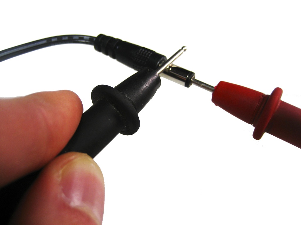
Black probe touches the barrel
- Plug your power supply into an AC outlet.
- Turn on your multimeter and set it to read DC voltage.
- Take the red (positive) probe from your multimeter and stick it into the end of the power supply plug as shown in Figure 5.
- Take the black (negative) probe from your multimeter and carefully touch it against the barrel of the plug without touching the tip or your red probe. If you make a connection, you will be creating a short circuit.
- On your multimeter you should see a reading of the voltage coming from your power supply. If you are checking a 12V power supply and your multimeter shows “12.56V” everything is fine and dandy as shown in Figure 6. If you get a reading of “-12.56V” then your probes are attached in reverse. If this happens and you are positive you connected your probes correctly, double check the polarity on your power supply’s label and make sure the circuit you will be powering with this unit is designed to handle this polarity.
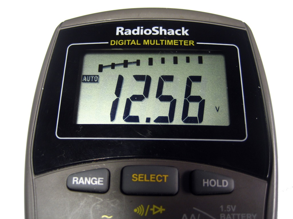
If the voltage showing on your multimeter is more than half a volt or a volt off its rating, then you most likely have what is called an unregulated power supply. The 12V Jameco power supply we used in this example is a regulated one, so that is why the voltage we received was so close to the voltage it was rated for. Some 12V DC power supplies will actually read at 15-16V.
Unregulated power supplies run high on voltage when there is no load. When the supply starts to take a load, the current consumed will go up, and the voltage will drop. There are (more expensive) constant current supplies and constant voltage supplies, which will adjust their current or voltage when there is a change in the voltage or current, respectively. For more on this, here’s a decent explanation.
This is a reason why we use voltage regulators, and why most microcontroller modules have them built in. They’re designed to take a range of voltage and output a constant, lower voltage. In a sense, a voltage regulator is a very minimal constant voltage supply.
Powering an Arduino Project from a Mobile Phone Charger
Many people have old mobile phone chargers around the house, and wonder, “Can I use this for powering an Arduino project?” Generally, you can. Just get a USB cable with the appropriate connectors to connect the phone charger to your Arduino. Most phone chargers output 5V and a few hundred milliamps, which will power an Arduino, some sensors, and some LEDs. If you try to program your Arduino from the phone charger’s cable, though, you may be out of luck. Many phone chargers come with USB cables that contain only the power connections, not the data connections.
Matching A Power Supply to an Electronics Device
To determine whether a power supply is right for your project, you need to note the voltages that each component operates at, and the current they consume, and make sure your power supply can provide the right amount of power.
Here are a few examples:
Arduino, Pushbuttons, Potentiometers, LEDs, Speaker
Imagine you’re making a project that includes an Arduino, a few LEDs, some pushbuttons, some potentiometers or other variable resistors, and perhaps a speaker. The Digital In and Out lab and the Analog In lab, and the Tone Output labs all describe projects that meet this description. All of the components other than the Arduino in this project are powered from the Arduino voltage output. None of the external components consume more than a few milliamps each. The whole circuit, Arduino included, will likely consume less than 200 milliamps of current. Here’s a breakdown, measured using an LED and a potentiometer:
- Arduino Uno, no external components: 0.04A (40 mA)
- Arduino Nano 33 IoT, no external components: 0.01A (10 mA)
- LED: 4 mA
- potentiometer connected as analog input: 0.29 mA
- 8-ohm speaker, playing a tone on the output pin: 0.5 mA
A phone charger, which supplies 5 volts and about 500 milliamps to the Arduino, would do the job fine. The Arduino Uno operates on 5 volts, and the Arduino Nano 33 IoT, which operates at 3.3 volts, has a built-in voltage regulator that will convert the 5V to 3.3V.
If you had a 12-volt supply like the one above, you could also use it for these projects. The Arduino Uno has a voltage in plug which matches it, and can take up to 15V. An on-board regulator converts the higher voltage input to 5V. The Nano 33 IoT has an on-board regulator that can accept up to 20V in its Vin pin (physical pin 15), so if you connected a DC power Jack and connected the ground of the 12-volt supply to the Arduino’s ground and the positive connection of the 12-volt supply to the Arduino’s Vin pin, your project would operate.
Arduino, Servomotor
If you’re controlling an RD servomotor from an Arduino as shown in the Servomotor lab, you need to consider the current a bit more. A servo like the Hitec HS-311 , which is popular in physical computing projects, operates at 4.8 – 6.0V, so it can get enough voltage from an Arduino’s voltage output. When it’s idle, it consumes about 160 mA with no load on it. It can consume up to 3-400 mA with a heavy load, however. It’s wise to plan your project for each component’s maximum current consumption, so a single servo and Arduino could consume up to 440 – 450 milliamps at 5 volts. That is almost the limit of what a laptop computer can supply via USB, and it’s the limit of some smaller phone chargers as well. If you were controlling multiple servos, you wouldn’t have enough current.
- Arduino Uno, no external components: 0.04A (40 mA)
- Arduino Nano 33 IoT, no external components: 0.01A (10 mA)
- HS-311, heavy load: 400 mA
Arduino, DC Motor or Lights
When you start powering larger DC motors, DC lights, or other high-current loads, you have to calculate the voltage and current before you select a power supply. You generally work from the component that has the highest consumption and work from there.
For example, controlling an LED light bulb like this one would require a 12V DC power supply for the bulb. It consumes 11 watts of power, and watts = volts * amps, so it consumes about 917 milliamps of current at 12 volts. The transistor and Arduino that might control it could be powered via the same 12-volt power supply, and would consume the same amounts as in the examples above.
Motor projects and addressable LED projects often consume the most electrical energy and are the most complex to power. A typical addressable LED like a WS2812, aka NeoPixel LED, consumes between 60 and 80 mA of current at 5 volts. When you have a string of 60 of them, that’s 3.6 amps of current! These definitely can’t be powered from a typical DC wall supply. When you reach that level of complexity with a project, consult your components’ datasheets or your instructors for more guidance. The videos on electricity, current, and power are helpful on this subject as well.