Introduction
In this lab you will learn about some of the components you’ll use frequently when making electronic circuits. For more on any given component, please check out its datasheet. There are no specific activities in this lab other than to examine the components and to familiarize yourself with them.
A datasheet or spec sheet is a document (printed or .pdf) that describes the technical characteristics of a sensor, electronic component, product, material or other. It includes details on how to use the component in a circuit and other useful design info on how to integrate it into a system together with specifications on performance and other characteristics that are important to know.
Components
Component or Package?
You’ll hear a few different terms for the parts you’re working with. A component is an electrical part that has a particular function, as described below. A component’s package refers to its physical form. The package is not dependent on what the actual part is. You’ll see a few components below that have the same package, like some of the voltage regulators and some of the transistors.
Voltage Regulator
Related Video: Voltage Regulator
Related Video: Using a voltage regulator on a breadboard
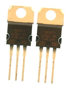
Different electronic circuits operate at different voltages. For example, the Arduino Uno operates at 5 volts, while the Arduino Nano 33 IoT and BLE, and the MKR series, operate at 3.3 volts. A voltage regulator takes a range of DC voltage as input and convert it to a constant voltage. For example, this regulator shown in Figure 1, a 7805 regulator, takes a range of 9 – 15 volts DC input and converts it to a constant 5-volt output. Using this regulator, you could power a 5-volt motor or a string of addressable LEDs from a 12-volt power source.
Note the label on the regulator that reads “7805”. This is the part number. Other parts have the same physical package, however. This is a TO-220 package. Many different parts use this same package, for example, and not all of them are voltage regulators. Also, sometimes the same part will come in different packages, so you can use it in different size devices.
Related Video: Read the labels to differentiate similar packages
The 7800 series regulators come in many different voltages. 7805 is a 5-volt regulator. 7809 is a 9-volt regulator. 7812 is a 12-volt regulator. All the regulators of this family have the same pin connections. In the image above, the left leg is connected to the input voltage. The middle leg is connected to ground. The right leg is the output voltage.
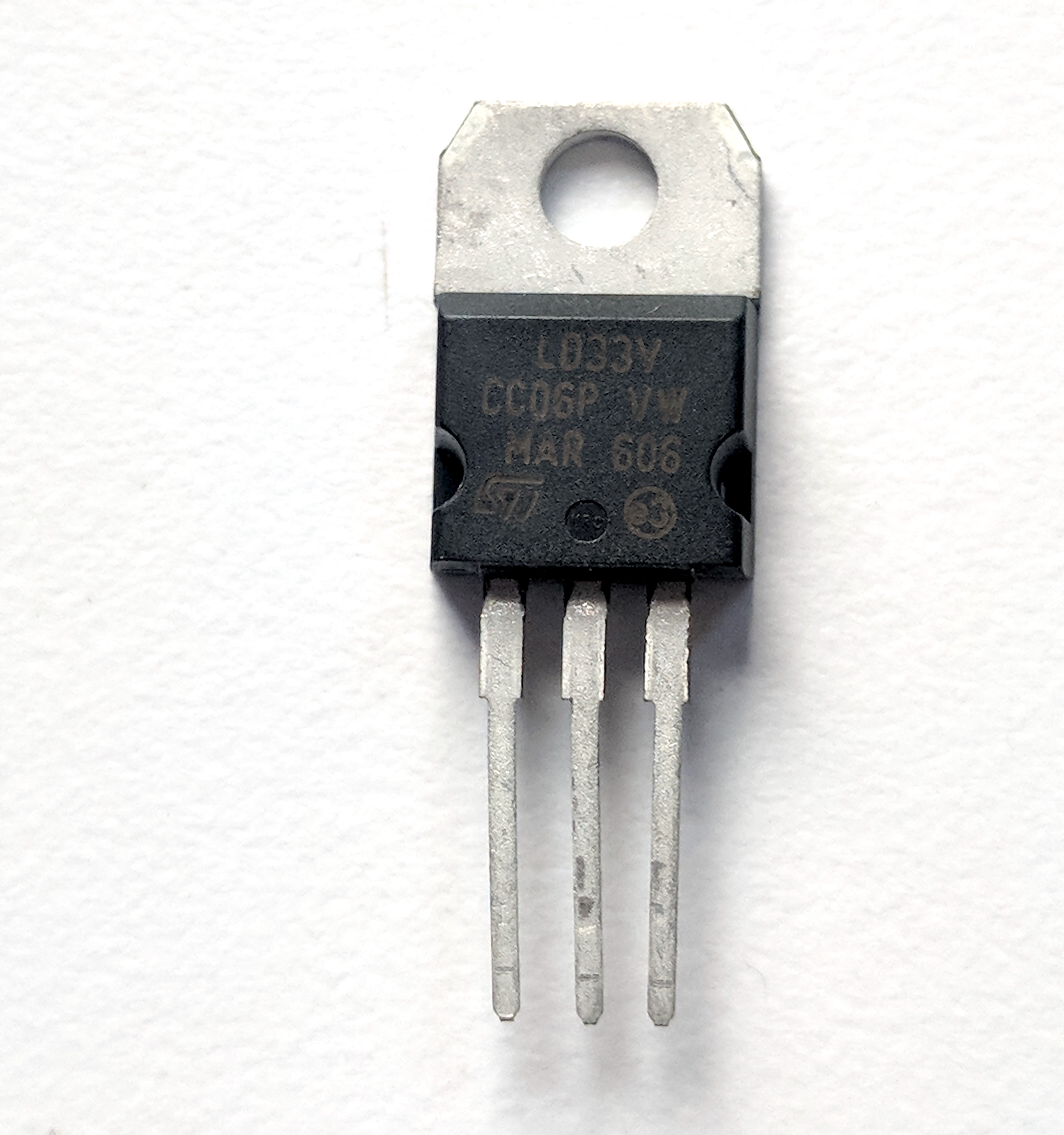
3.3V regulators are also common. Note that not all regulators which share the same package have the same pin configuration. For example, the LD1117V33, a 3.3V regulator shown in Figure 2, comes in the same physical package as a 7805, but its pins are in a different order. The LD1117V33’s pins, from left to right, are ground, output voltage, input voltage.
LED

Related Video: Diodes and LEDs
LEDs, or Light Emitting Diodes (see Figure 3), are diodes that emit light when given the correct voltage and current. Like all diodes, they are polarized, meaning that they only operate when oriented correctly in the circuit. The anode of the LED connects to voltage, and the cathode connects to ground. The anode in the LEDs in this photo is the longer leg on each LED. LEDs come in many different packages. The packages above have built-in lenses.
Related Video: How to connect an LED and resistor
These LEDs are the cheapest you can buy, and they’re not very bright. You can get super-bright LEDs as well, which are much brighter. If you’re working on applications that need very small light sources, you can also get LEDs in a surface mount package.
LEDs can only handle a limited amount of current and voltage. The details should be covered in each LED’s datasheet. Here is the datasheet of a typical white LED. You’ll see that the forward current is 30 mA max, and the forward voltage is between 2.9 and 3.6V. That means if you give it 30mA at 3.6V, you should get maximum brightness out of it. If you don’t have the datasheet for your LED, here’s a link to a handy LED current calculator. Try putting in the supply voltage (3.3V or 5V), the voltage drop across the LED (the forward voltage), and the current (30 mA) and see what value of resistance you get. For most common LEDs running at 3.3 or 5 volts, a resistor about 220 will limit the current safely while still providing enough to light the LED.
Solderless Breadboard

Related Video: Introduction to breadboards
Solderless breadboards are reusable prototyping tools for electronics that allow you to build and experiment with circuits simply by plugging components in and out of its rows and columns. They come in different shape and sizes. Figure 4 shows a typical short solderless breadboard. It has two rows of holes on either side of the board, usually used as voltage and ground buses. The board is turned in this photo so that the bus rows are on top and bottom. In the center of the board, there are thirty rows of holes. There is a divider down the center of the board that breaks up the rows of holes into separate rows. There are five holes per row on the center left and on the center right of each row.
Resistors

Related Video: Resistors, variable resistors, and photocells
Resistors resist the flow of electrical current. When placed in series, they reduce the voltage, and limit the current. The bands on a resistor indicate the resistor’s value. Here’s a handy resistor color code calculator. Resistors come in 4-band, 5-band, and 6-band models. In a 4-band resistor, the bands represent the first digit, second digit, multiplier, and tolerance. The resistors shown in Figure 5 are 4-band resistors marked red, red, brown, and gold, for 2, 2, times 101, 5%. In other words, these are 220 ohm resistors, +/-5%. The resistor color code calculator explains the bands for 5-and 6-band resistors as well.
Potentiometers
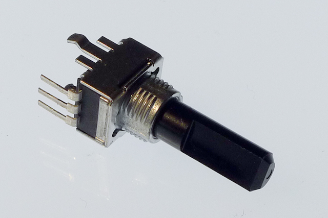
Potentiometers are variable resistors. The two outside terminals act as a fixed resistor. A movable contact called the wiper moves across the resistor, producing a variable resistance between the center terminal and either of the two sides. The potentiometer in Figure 6 has pins so you can mount it on a breadboard.
Related Video: Measure a potentiometer’s variable resistance
Related Video: Potentiometer schematic
Trimmer potentiometers like those shown in Figure 7 are designed to be mounted on a circuit board, and are difficult to turn, so you can use them to adjust a circuit. They’re very small. They’re handy to use as physical variables, to tune your project.
Force Sensing Resistors
Force sensing resistors are sensors that change their resistance in response to force. They’re usually used to make analog alternatives alternatives to buttons. They’re made of a substrate of resistive rubber between two layers of conductive ink on a plastic film. They come in a variety of form factors. Figure 8 shows a pair of force sensors about 2.5cm across, sized for finger presses. There are a few companies who make them, including Interlink, Ohmite, and Tekscan.

Flex Sensors (Flex Resistors)
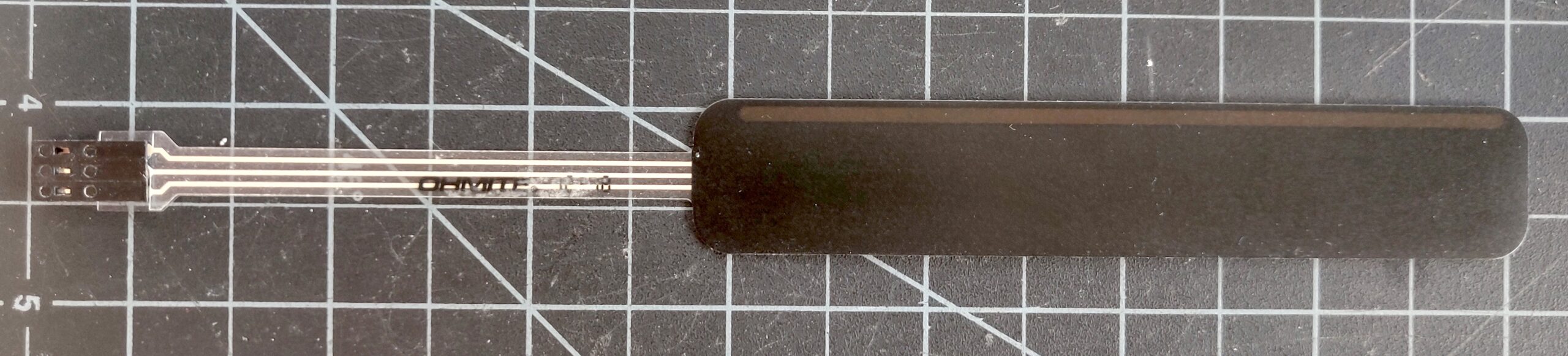
Flex sensors are similar to force sensing resistors in construction, but they change their resistance as they bend. They are typically about the length of a finger, and they work well for measuring the bend of a finger. Spectrasymbol make these.
Force Sensing Potentiometers
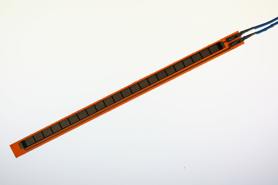
Force Sensing Potentiometers, sometimes called SoftPots, are also similar to force sensing resistors. The difference is that a force sensing resistor gives one value wherever you press on it, while a force sensing potentiometer acts like a normal potentiometer: the value changes depending on where along its length you press. They come in linear and round form factors. Ohmite, Interlink, and Spectrasymbol make FSPs.
Light-Dependent Resistors (Photocells)
Related Video: Wiring a photocell to measure light
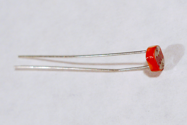
Light-dependent resistors, or photocells, are variable resistors whose resistance changes with the intensity of the light falling on the resistor. Photocells, as seen in Figure 11, are made with cadmium sulfide, which is a toxic chemical. Increasingly, they are being replaced in hobbyist kits by phototransistors, which are somewhat less toxic (see below).
Thermistors
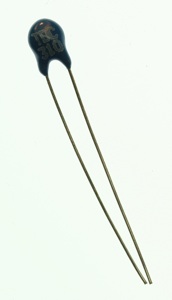
Thermistors, seen in Figure 12, are variable resistors whose resistance changes as the temperature changes. You measure the resistance between the two legs of the thermistor and expose the top to a varying temperature in order to vary the resistance between the two legs.
Switches
Related Video: Switches
Related Video: Connect a switch to a digital pin
Switches are one form of digital input. There are many kinds of switches. The two most useful categories are momentary switches, which remain closed only when you press them, and toggle switches, which stay in place after you switch them.
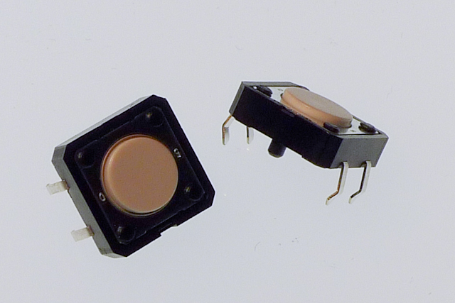
Pushbuttons are a common type of momentary switch. The pushbuttons in the photo in Figure 13 above are designed to be mounted on a circuit board. They are very small, less than 1 centimeter on a side. They have four pins. When the button is facing you, top two are connected to each other, and the bottom two are connected to each other. Pushing the button connects the top pins to the bottom pins.
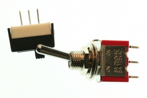
Toggle switches (Figure 14) stay in one position when you flip them. Wall light switches are common examples of toggle switches. Unlike a momentary switch, a toggle switch can be used to turn a device on or off, because they stay in one state when you remove your hand. The toggle switches below each have three connectors, also called pins or legs. They’re usually labeled C for common, NO for Normally Open, and NC for Normally Closed. When you switch the switch, it will open the connection between the common pin and the normally closed pin, and close the connection between the common pin and the normally open pin. Switch it the other way, and you will reverse the connection.
Rotary Encoder
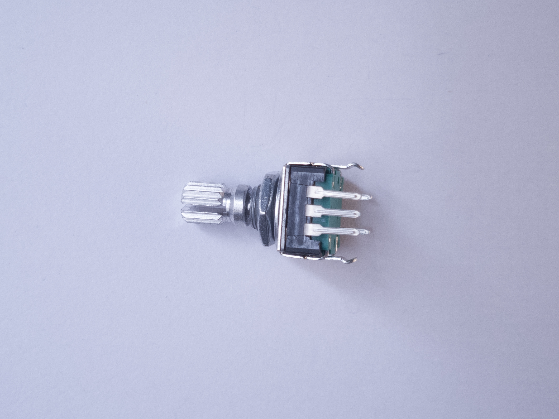
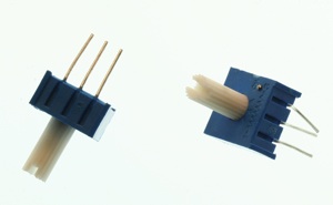
A rotary encoder is a sensor that usually looks a bit like a potentiometer. It has a central shaft that you can turn with your fingers, or with an axle. It produces a pair of electrical pulses as you turn the shaft of the encoder, one slightly before or after the other, depending on the direction you are turning the shaft. Unlike a potentiometer, they can turn endlessly. They are used both as tangible controls, when you want a knob that turns endlessly, and as rotary sensors for motors and axles. The encoder in Figure 15 has three pins. The center is connected to ground, and the two side pins produce the pulses. The Encoder library for Arduino is useful for reading these.
Capacitors
Capacitors store electrical energy while there’s energy coming in, and release it when the incoming energy stops. They have a variety of uses. One common use is to smooth out the dips and spikes in an electrical supply. This use is called decoupling.
Related Video: Clean a noisy signal with a Capacitor
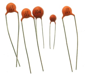
Ceramic capacitors are unpolarized. They generally have very small capacitance values. They’re useful decoupling caps in a low-current circuit. You often see them used to decouple the power going into a microcontroller or other integrated circuit.
The number on a ceramic cap gives you its value and order of magnitude. For example, 104 on the capactors in Figure 16 indicates a 0.1 microfarad (uF) cap. 103 indicates a 0.01 microfarad cap.
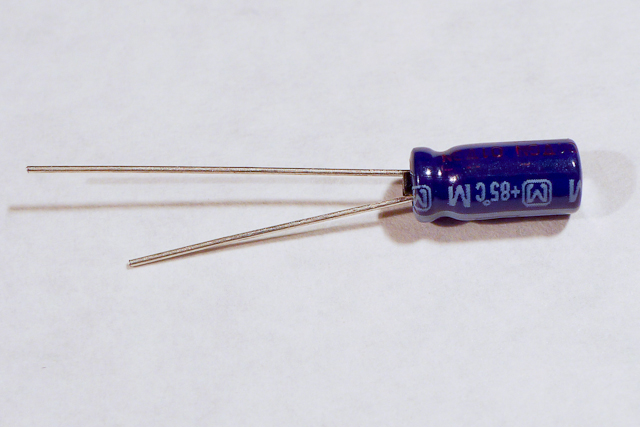
Electrolytic capacitors (Figure 17) can generally store more charge than ceramic caps, and are longer lasting. They’re usually polarized, meaning that they have a positive leg and a negative leg. This is because current flows more efficiently through them one way than the other.
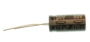
An electrolytic cap will have a + or – on one side, as shown in Figure 18.
Diodes
Related Video: Diodes and LEDs
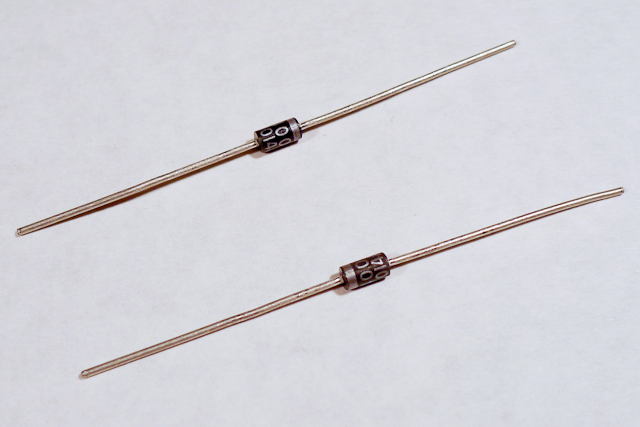
Diodes permit voltage to flow in one direction and block it in the other direction. LEDs are a type of diode, as are the 1N4001 diodes shown in Figure 19. They’re useful for stopping voltage from going somewhere you don’t want it to go. The 1N4001 diodes are power diodes, capable of carrying a higher amount of current than other diodes.
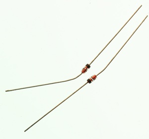
Zener diodes (Figure 20) have a breakdown voltage past which they allow current to flow in both directions. They’re used to chop off excess voltage from a part of a circuit. They are usually smaller than power diodes.
Transistors
Video: Schematics 3 – Transistors
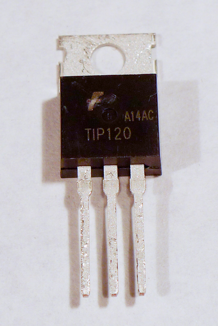
Transistors act as electronic switches. When you put a small voltage across the base and emitter, the transistor allows a larger current and voltage to flow from the collector to the emitter. The transistor shown above in Figure 21, a TIP120, is a type of transistor known as a Darlington transistor. It is usually used to control high-current loads like motors. Note that it uses the same physical form factor, or package, as the voltage regulator above (the TO-220 package).
The TIP120 shown here is jus one option for controlling high current loads. Metal Oxide Semiconductor Field Effect Transistors, or MOSFETS, are also good for controlling motors, lights, and other high current loads. These two models also come in the same physical package as the TIP120. The IRF510 and IRF520 MOSFETs have the same pin configuration as the TIP120, and perform similarly with a 5V gate voltage. The FQP30N06L MOSFET has the same pin configuration, and operates on as low as 1.0V, and works well for 3.3V applications. MOSFETs can generally handle more amperage and voltage, but are more sensitive to static electricity damage.
Related Video: Connect Transistor
Phototransistors
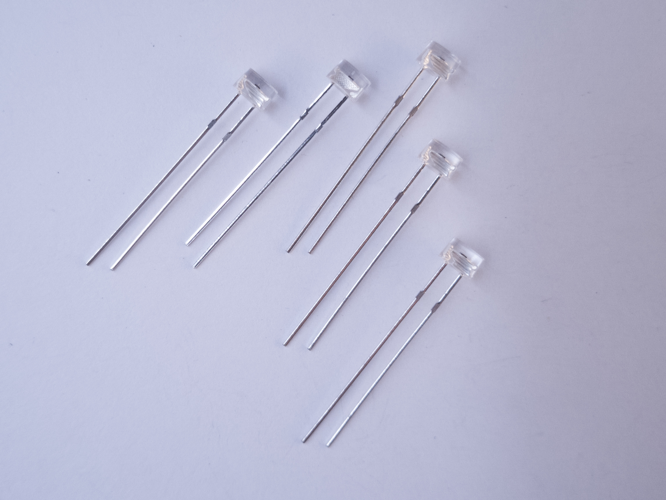
Phototransistors are transistors, but instead of being controlled by electricity, they are controlled by light. The base of a phototransistor is photosensitive. They often look like LEDs. The ones in Figure 15, Everlight model ALS-PT243-3C/L177, have flat tops to differentiate them from LEDs. The short leg of a phototransistor is the emitter, and the long leg is the collector. The lens is the base. To use them in an analog input circuit. emitter goes to voltage and the collector goes to your input pin. A 10-kilohm pulldown resistor connects the input pin to ground, just as it would if you were using a photocell..
Power Jacks
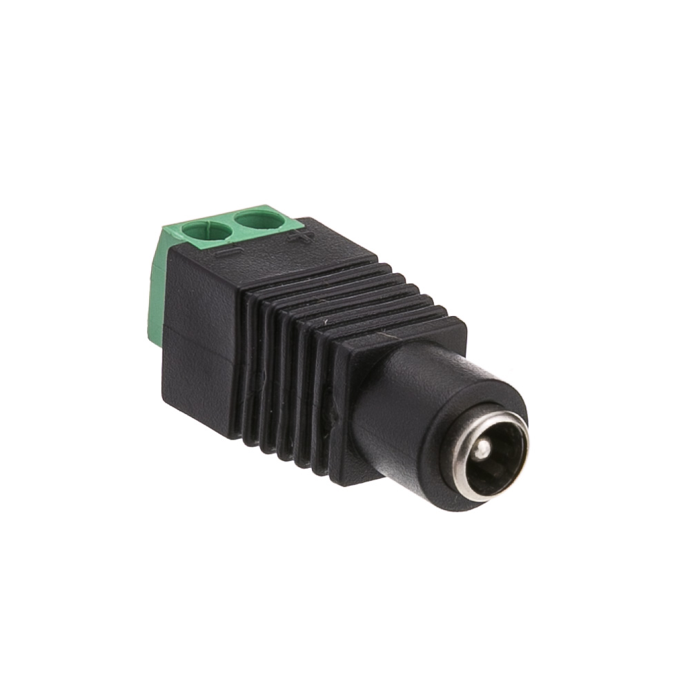
DC Power jacks are used to connect your breadboard to a DC power supply that you can plug into a wall. They’re less common in microcontroller circuits now that USB power connectors and USB wall plugs are common, but they are still very handy when you have only a DC power supply to work with. The one in Figure 22 has screw terminals on the back to which you can connect wires to connect to your breadboard. It is a 2.1mm inside diameter, 5.5mm outside diameter jack, which is a very common size.
Battery Holders
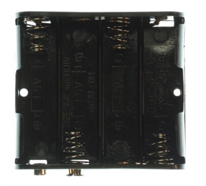

Battery connectors like the ones shown in Figures 23 and 24 are good for connecting batteries to your project. The one in Figure 20 can hold 4 AA batteries, and has a 9V battery snap on the outside. The one in Figure 21 has a DC power jack on one end, and a 9V battery snap on the other end.
Motors
Servo Motor
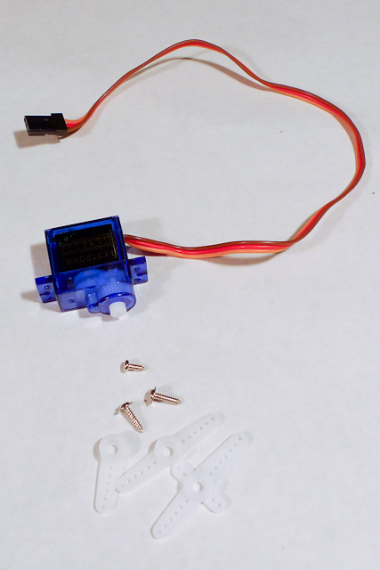
A servo motor is a motor paired with an encoder (e.g. a potentiometer) to provide position/speed readings and control messages in a feedback loop. This loop is used to precisely control of the servo’s degree of rotation. RC servomotors like the one shown in Figure 25 can only turn 180 degrees. They are often used for the rudder control on remote control planes and cars. The plastic bits shown in the photo are called horns, and they attach to the shaft to let you attach the motor to the mechanism that you want to control.
DC Motor
Related Video: Inside a DC Motor
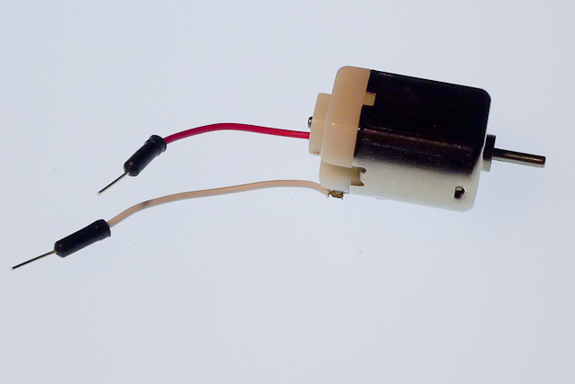
DC motors, as seen in Figure 26, utilize induction (an electromagnetic field generated by current flowing through a wire coil) to rotate a central shaft. You can reverse the direction that the shaft rotates by reversing the leads powering it.
Motor Driver
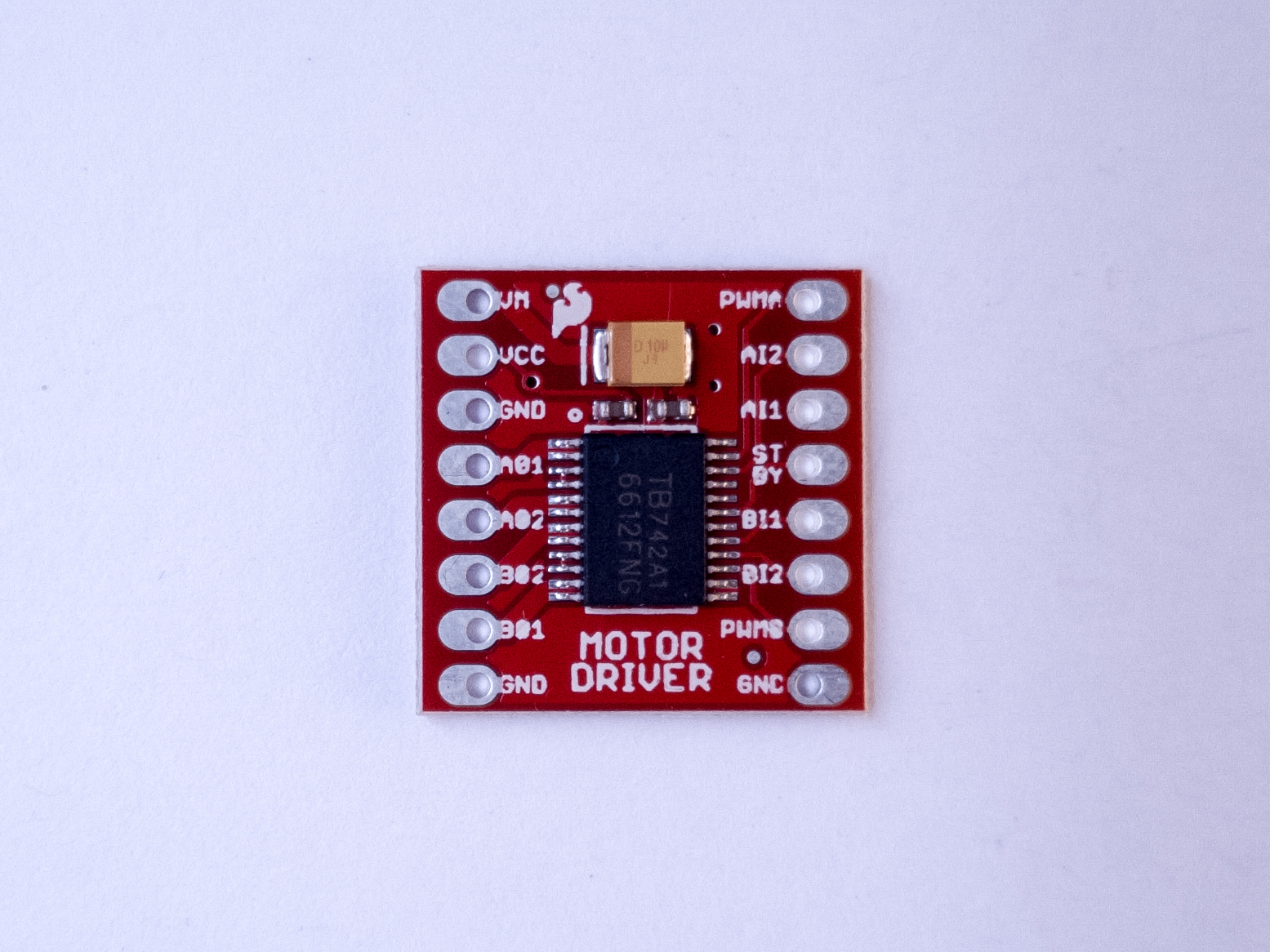
A motor driver, sometimes called an H bridge, is an electronic circuit that enables a voltage to be applied across a load in either direction. They are often used to control the direction of DC motors. The motor driver in Figure 27 is a Toshiba model TB6612FNG. It is a good option for both 5V (from an Arduino Uno) and 3.3V (from a Nano 33 IoT) control of DC motors and stepper motors.
Electromechanical Relay

Like transistors, relays are electronic switches. Electromechanical relays contain a small coil that, when energized, creates a magnetic field that moves a small metal armature to open or close an electrical contact. Relays can handle higher current than transistors and can be used for AC or DC loads. However, because they rely on a physical mechanism, they are slower and more prone to wearing out. If you want to control a relay with the Arduino, you will need to use a transistor as an intermediary because most relays draw more current than the Arduino’s output pins can supply.
Relays come in many packages. The ones shown in Figure 28 are for controlling relatively low power loads. For more on relays, see the Transistors, Relays, and Controlling High-Current Loads topic page.
Screw Terminal
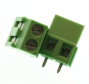
Screw terminals, as seen in Figure 29, are electrical connectors that hold wires in place with a clamping screw. They allow for a more secure connection than female headers and more flexibility than soldering a wire in place. There is one screw, socket, and pin per connection.
Sensor Modules
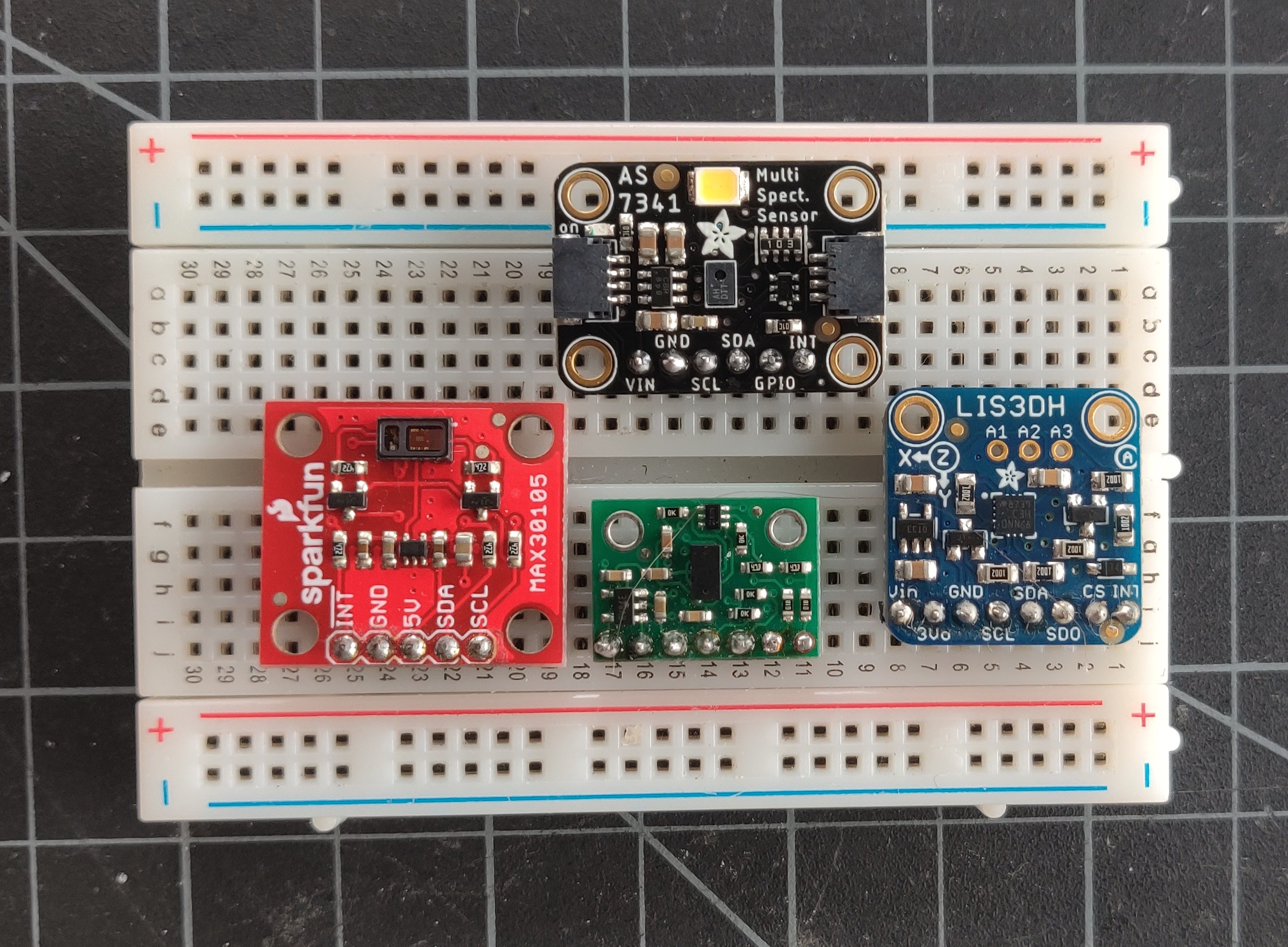
Increasingly, sensors are no longer just simple components that output a changing resistance or capacitance. Sensor modules are application-specific integrated circuits (ASICs) which read a particular physical property and give you a measurement via a synchronous serial communications channel like I2C.
Figure 30 shows four different I2C sensors: a ten-channel spectrometer, at the top, which measures the intensity of light in ten different frequencies; An accelerometer, on the right (read below for more); a time-of-flight distance ranging sensor, that measures distance using an infrared low-power laser, on the bottom; and a light sensor that functions as both a particle sensor and a pulse oximeter, on the left, by measuring the change in color of your blood through the skin of your finger.
These are only a few of the many sensor modules available that can be connected to a microcontroller via I2C. You’ll see color and gesture sensors, temperature and humidity sensors, and many more. They are often available as breadboard-friendly breakout board modules, like the ones shown here, that are typically a circuit board that’s a few centimeters square, with holes on one side spaced 0.1″ apart so you can attach pins to plug it into a breadboard.
Accelerometer
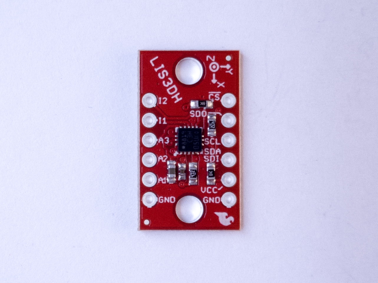
Accelerometers are sensors which measure a changing acceleration (Figure 31). They are typically part of sensors called Inertial Measurement Units, or IMUs. They are useful for measuring the tilt of a body, or for measuring the force of an impact. They come in both digital and analog forms. A typical accelerometer measures acceleration along three axes, all perpendicular to each other. Accelerometers are increasingly built into microcontroller modules and other electronic devices. There is accelerometer and a gyrometer built into the Nano 33 IoT.
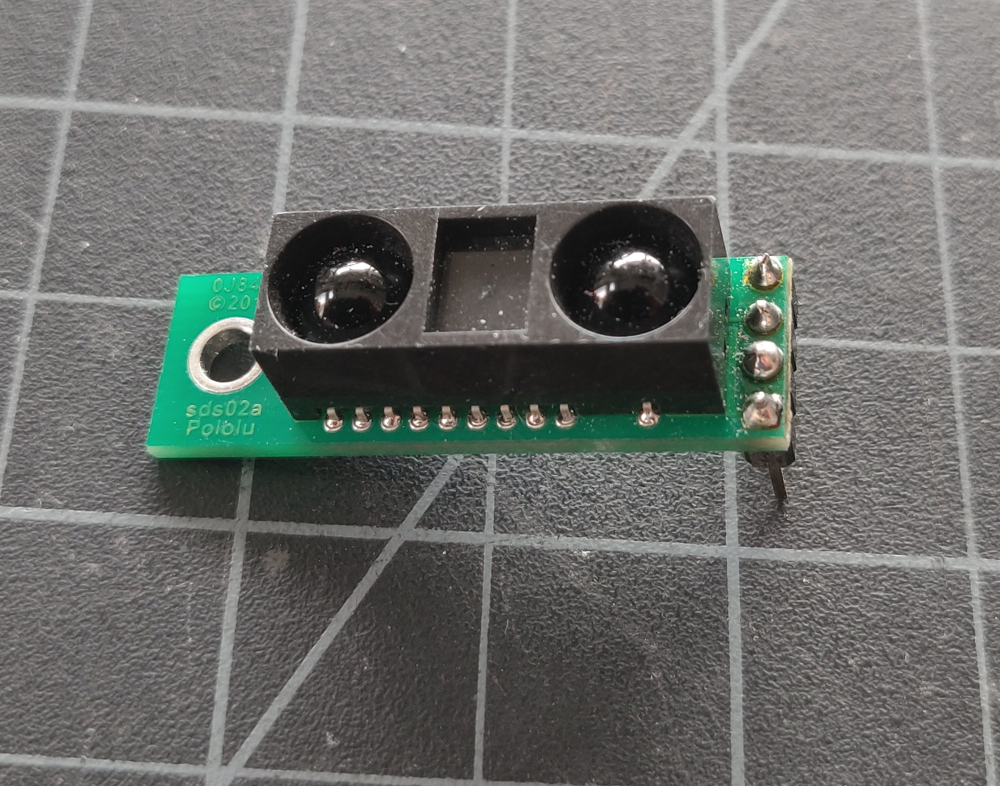
Infrared Distance Ranger
Sharp makes a line of infrared distance ranging sensors that measure distance in about a 1-meter range using infrared light. The one shown in Figure 32 has an analog voltage output.
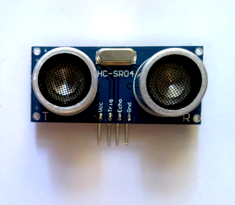
Ultrasonic Distance Ranger
Ultrasonic distance rangers measure distance by emitting pulsed ultrasonic waves and listening for the echo from a distant object. These are sometimes used in cars to aid in detecting the distance of objects behind the rear bumper. The one shown in Figure 33 outputs a digital pulse whose pulse width varies with the distance from the target object.
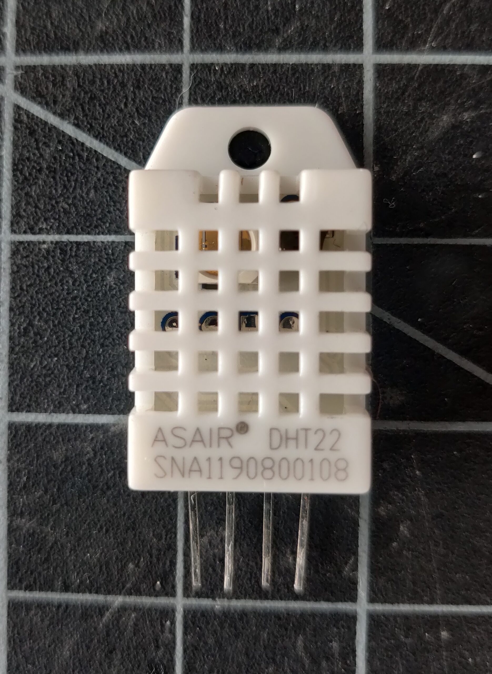
Temperature and Humidity Sensors
There are dozens of temperature and humidity sensors on the market, with many different interfaces. The one shown in Figure 34, the DHT22, is very popular because it’s simple to use, reliable with a long track record, and inexpensive. It uses a one-wire interface.
Speaker

A speaker is a paper or plastic cone mounted to a coil of wire. The coil is mounted next to a magnet. When a current is passed through the wire, it induces a magnetic field, which attracts or repulses the magnet. This makes the cone vibrate, and produce sound. The speaker shown in Figure 35 is an 8-ohm speaker.