Introduction
Related Video: Intro to Synchronous Serial
Asynchronous serial communication, which you can see in action in the Serial Output lab, is a common way for two computers to communicate. Both computers must have their own clock, and keep time independently of each other. This works well for personal computers, mobile devices, and microcontrollers because they all have their own clock crystal that acts as the processor’s heartbeat. However, there are simpler integrated circuits that have only one function, such as to read a sensor or to control a digital potentiometer or an oscillator to drive a PWM circuit. These ICs have no clock crystal of their own. They consist of a few memory registers and the minimal circuitry needed to connect these memory registers to the circuit that they control. To communicate with these ICs, you need to use synchronous serial communication.
To get the most out of these notes, you should know what a microcontroller is and have an understanding of the basics of microcontroller programming. You should also understand the Asynchronous Serial Communication: The Basics as well.
Synchronous serial communication protocols feature a controller device which sends a clock pulse to one or more peripheral devices. The devices exchange a bit of data every time the clock changes. There are two common forms of synchronous serial, Inter-Integrated Circuit, or I2C (sometimes also called Two-Wire Interface, or TWI), and Serial Peripheral Interface, or SPI.
Synchronous serial devices communicate by shifting bits of data along their communication lines, like a bucket brigade. Data moved down the line one bit every time the clock pulses. All the devices in a synchronous serial chain share the same data and clock lines. Peripheral devices are directed by the controller device when to listen to the bits coming down the line, and when to ignore them. However, the two most common synchronous serial protocols, SPI and I2C, use different methods for directing the peripheral devices.
Serial Peripheral Interface (SPI)
Related Lab: SPI Communication With A Digital Potentiometer
SPI devices are connected by four wires, as shown in Figure 1:
- a Serial Data In (SDI), on which the controller sends data to the peripheral devices.
- a Serial Data Out (SDO), on which the peripheral devices send data to the controller.
- a Clock (SCLK) connection, on which the controller sends a regular clock signal to the peripheral devices.
- one or more Chip Select (CS) connections, which the controller uses to signal the peripheral devices when to listen to incoming data and when to ignore it.
A Note on Pin Naming
The electronics industry has used the terms “master/slave” to refer to controller devices and peripheral devices for decades without regard for the historical context of, and offense caused by, those terms. As a result, you will see the terms MOSI/MISO/SS in data sheets to refer to the pins of an SPI device. While a modern standard naming scheme has not yet emerged to replace these, the Open Source Hardware Association has a proposal on the table. Make Magazine proposes retaining the acronym while renaming the terms. The SDO, SDI and CS terms are currently used by a handful of companies within the industry, but have some ambiguity when used in practice. Hence, the PICO/POCI proposal. The debate is not resolved, and you will likely see some variations on the terms. The SDO, SDI, and SCK terms are the most widely accepted terms that do not carry historical baggage.
The SDI, SDO, and SCLK connections are shared between all the devices connected to the controller. This configuration is called a bus. Each peripheral has its own dedicated Chip Select connection to the controller, however.
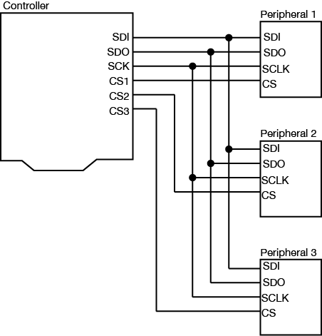
Figure 1. A typical SPI bus configuration. The Controller’s output (SDO) is the peripherals’ input (SDI) and vice versa. Each peripheral gets its own Chip Select line. All other lines are shared.
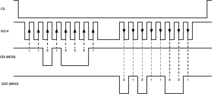
When the controller device wants to communicate with one of the peripherals, it sets that device’s Chip Select pin low. The peripheral will then listen for new bits of data on the microcontroller’s Serial Data Out (SDO) line every time the clock changes from low to high (called the rising edge of the clock). If it is instructed to send any data back, it will send data back to the controller when the clock signal changes from high to low (called the falling edge of the clock). When a peripheral device’s Chip Select pin is high, it will not respond to any commands sent on the data line.
The data exchange between SPI devices is usually shown like this (Figure 2):
The Arduino’s SPI pins are determined by the processor. You can find the pins for the various models on the SPI library reference page. For the Arduino Uno, the pin numbers are pin 11 for SDO, pin 12 for SDI, and pin 13 for Clock (SCK). Pin 10 is the default Chip Select pin (SS), but you can use other pins for Chip Select as needed. The Arduino SPI library allows you to control the SPI bus. Most SPI devices that are compatible with Arduino come with their own libraries, however, which wrap the SPI library in commands specific to the device in question.
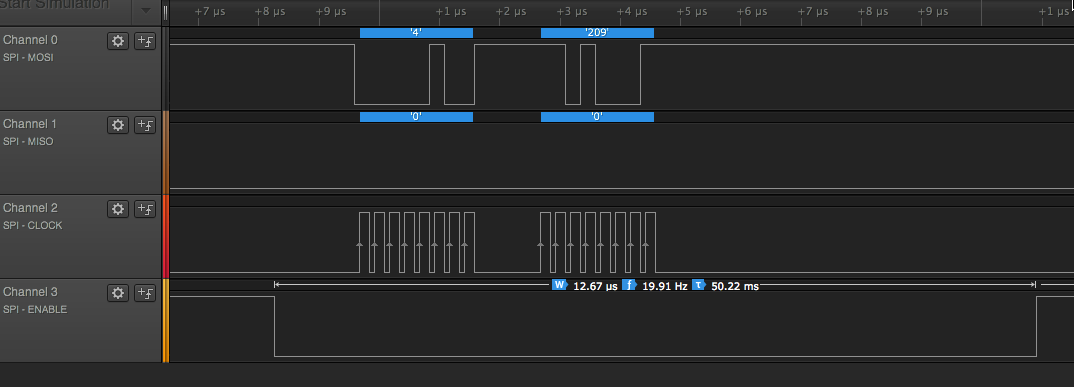
For example, the Analog Devices ADXL345 accelerometer can communicate via SPI. Its protocol works as follows: first the controller sets the ADXL345’s Chip Select (CS) pin low, then sends a command to the ADXL345 on the SDI line to enter measurement mode. The ADXL345 then continually samples the accelerometer and stores the latest readings in three memory registers. When the controller wants to know those values, it sets the Chip Select (CS) pin low and sends a request to read those memory registers. The ADXL345 responds by sending back the contents of the memory registers on the SDO line. When all the data has been received, the controller sets the Chip Select pin high again.
The advantage of SPI is that the data transactions are simple: all you need to do is to send the data to the device you’re communicating with. The disadvantage is that the number of wires needed to connect goes up by one for every peripheral device you add to the bus.
Inter-Integrated Circuit (I2C) or Two-Wire Interface (TWI)
Related Lab: I2C Communication With An Infrared Temperature Sensor
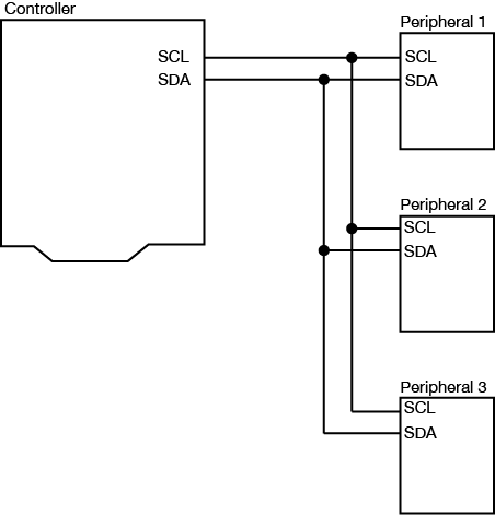
I2C is another popular synchronous serial protocol. It also uses a bus configuration like SPI, but there are only two connections between the controller device and the peripheral devices as shown in Figure 4:
- a Serial Clock (SCL) connection, on which the controller sends the clock signal, just as in SPI
- a Serial Data (SDA) connection, on which the controller and peripherals exchange data in both directions.
Each I2C peripheral device has a unique address on the bus. When the controller wants to communicate with a particular peripheral, it sends that peripheral’s address down the SDA connection, transferring each bit on the rising edge of the clock. An extra bit indicates whether the controller wants to write or read to the peripheral that it’s addressing. The appropriate peripheral then goes into listening mode, and the controller sends a command to the peripheral. Then the controller switches its connection to the SDA line from output to input. The peripheral then replies with the appropriate data, sending each bit on the falling edge of the clock. The controller switches its connection on the SDA line back to output once it’s received all of the data.
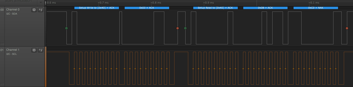
The I2C data capture in Figure 5 is typical (click to enlarge it). This is from a Texas Instruments TMP007 temperature sensor. The peripheral’s address is 0x40. First the controller sends a byte with 0x40 + 0 in the final bit, indicating that it plans to write a command to the peripheral. All of this data is sent valid on the rising edge of the clock. Then the controller sends a command, 0x03, which means “tell me your object’s temperature” to this particular IC. Then the controller sends a byte with the peripheral’s address again, 0x40 +1 in the final bit, indicating that it wants to read from the peripheral. The peripheral responds with two bytes, 0x0B and 0xC0. The controller then puts those two bytes together to get the object’s temperature (see the TMP007 datasheet if you want to know more)
The Arduino’s I2C pins are determined by the processor. You can find the pins for the various models on the Wire library reference page. The Arduino Wire library allows you to control the I2C bus. For the Arduino Uno, the pin numbers are analog pin 4 for SDA and analog pin 5 for SCL. On the Uno rev.3 layout, SDA and SCL are also broken out on the digital side of the board, next to the ground pin. Most I2C devices that are compatible with Arduino come with their own libraries which wrap the Wire library in commands specific to the device in question. For example, Adafruit‘s library for the TMP007 relies on the Wire library to transmit and receive data.
I2C Control of Multiple Microcontrollers
You can also use I2C as a way to control many microcontrollers from one central controller. For example, if you needed to operate a large number of servomotors, you could put five or six each on a single Arduino, then chain several Arduinos together in an I2C chain and program them all to respond as peripherals. Then you would program a central microcontroller as the controller, and have it send commands to the peripheral devices when it’s time to move each device’s servos. You can see an example of how to do this in this example from the Arduino site.
What are Qwiic/Stemma/Grove/Gravity?
In addition to the standard I2C connections, Sparkfun and Adafruit use a connector called Qwiic which connects the I2C and power connectors all in one cable, eliminating the need for soldering. It’s a Sparkfun brand name. However, you’ll need a Qwiic adapter shield to use it. Adafruit have a similar brand called Stemma, Seedstudio uses Grove, and DFRobot uses Gravity. They all support I2C, and they all have custom solderless connectors, though they are not all compatible with each other Qwiic, Stemma, and Arduino’s Modulino connectors work pretty well together, though. For an example of Qwiic connectors in action, see this lab introducing the Nano Qwiic shield.
Conclusion
SPI and I2C are useful protocols because they allow you to interface with a wide variety of sensor and actuator ICs without having to use many of your microcontroller’s IO pins. Because they are both bus protocols, you can chain many devices on the same bus, and call on them only when needed from your microcontroller. For more on their usage, see the Lab: SPI Communication With A Digital Potentiometer and the Lab: I2C Communication With An Infrared Temperature Sensor.