Introduction
In this lab, you’ll see synchronous serial communication in action using the Serial Peripheral Interface (SPI) protocol. You’ll communicate with a digital potentiometer chip from a microcontroller. You’ll use the digital pot to control the loudness of a speaker playing a tone from the microcontroller.
Related videos: Intro to Synchronous Serial, SPI
What You’ll Need to Know
To get the most out of this Lab, you should be familiar with the basics of programming an Arduino microcontroller. If you’re not, review the Digital Input and Output Lab, and perhaps the Getting Started with Arduino guide. You should also understand asynchronous serial communication and how it differs from synchronous serial communication.
Things You’ll Need
From Figure 1-5 are the parts that you need for this lab.


Controlling the Loudness of a Speaker
If you did the tone lab on this site, you know that it’s not possible to vary the loudness of a tone generated from a microcontroller. In order to change the loudness, you’d need to change the voltage of the tone pin. If you put a potentiometer in series with the speaker as shown below, you can modify the tone’s loudness, as is shown in Figure 6.
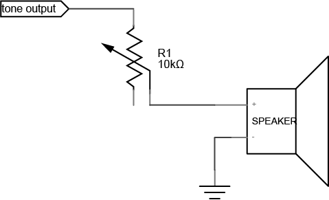
This circuit requires that you modify the loudness manually, by turning the pot. But with a digital potentiometer, you can modify the loudness from your program.
Connect the digital potentiometer
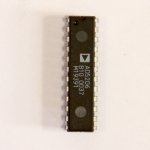
The digital potentiometer used in this lab, an Analog Devices AD5206, is an integrated circuit (IC) that can perform one specific function: it has six potentiometers that you can control, as is shown in Figure 7. Each of its pins has a specific function, as shown below. It’s in a Dual Inline Package, or DIP. DIP package ICs typically have their pins enumerated in a U-shape, starting with pin 1 on the top left, and the highest number pin on the top right.
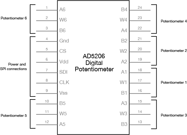
The potentiometers in this chip are labeled A1, B1, W1 through A6, B6, W6. The A and B pins are the fixed end pins of the potentiometer, and if you measure resistance across them with a multimeter, you’ll measure 10 kilohms. The W pins are the wipers, and the resistance is programmable via the SPI connection. You can use any of these potentiometers in a circuit just like you would a regular potentiometer.
First, connect the digital potentiometer’s power and ground connections, and the connections for clock, chip select, and serial data in, as shown in Figure 8-10:
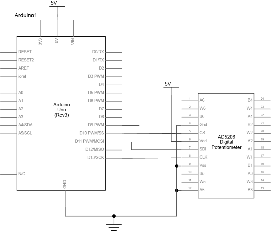
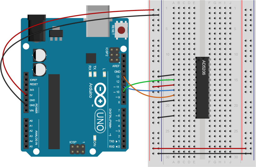
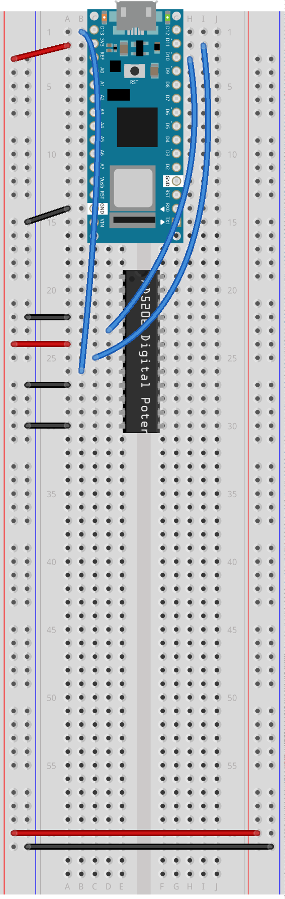
Figure 10. Schematic of an Arduino attached to a AD5206 Potentiometer. The Arduino’s ground is attached the the potentiometer’s A5, Vss, and Ground pins, numbered 12, 9, and 4, respectively. The Arduino’s D10, D11, and D13 pins are attached to the potentiometer’s CS, SDI, and CLK pins, which are numbered 5, 7, and 8, respectively. The potentiometer’s Vdd pin, number 6, is connected to 3.3 volts.
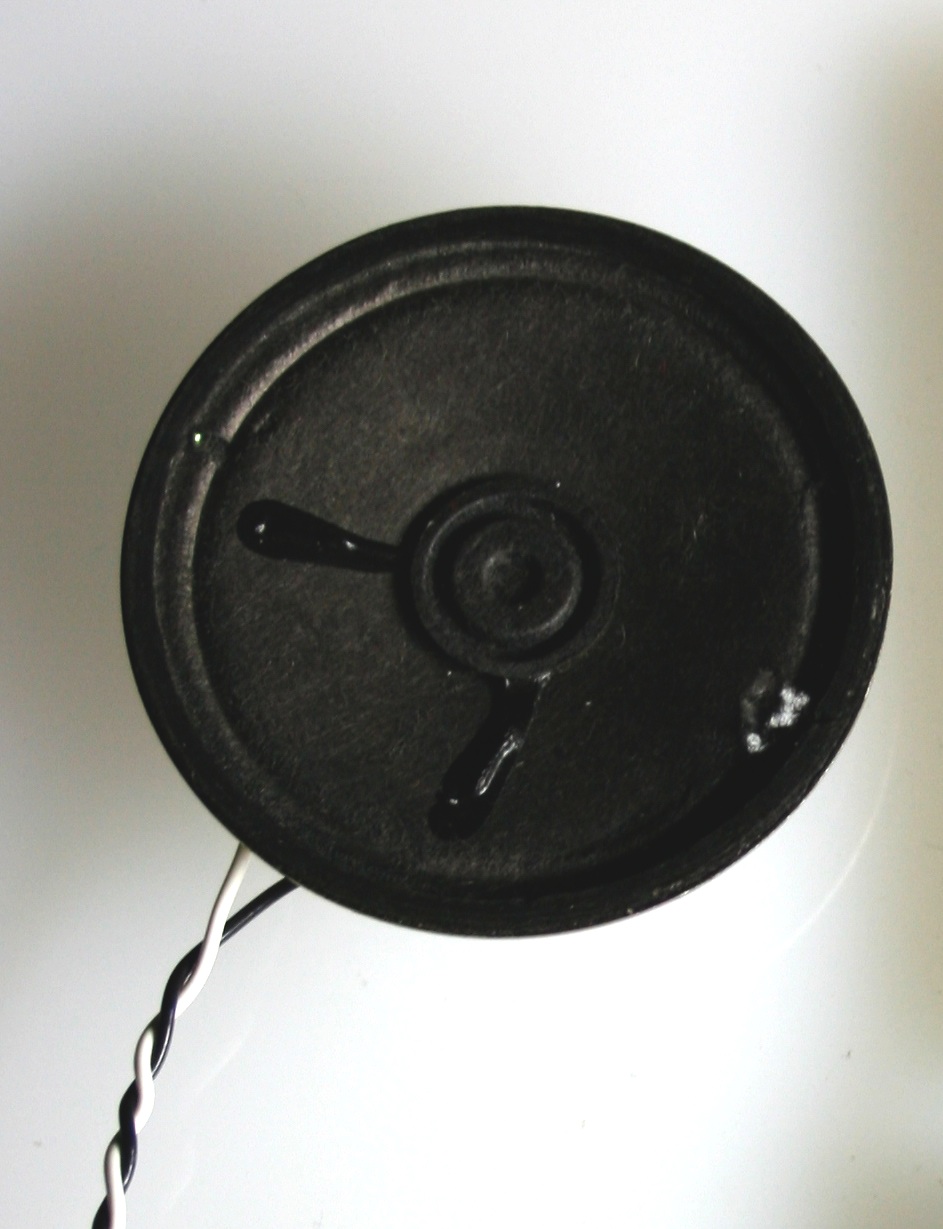
Next, add a speaker to the wiper of the fifth channel of the digital pot. Include a 100-ohm resistor in series with the speaker. Then connect the A5 pin to digital pin 9 of the Arduino, which you’ll use to generate a tone. You can use any channel of the digital pot if you want, but the code below uses the fifth channel.
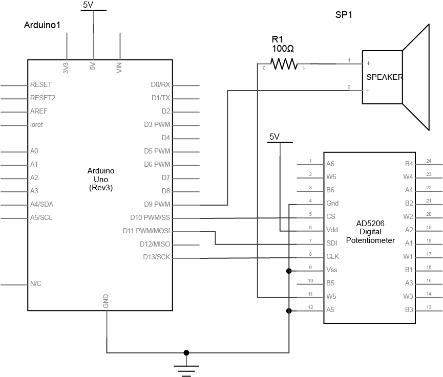
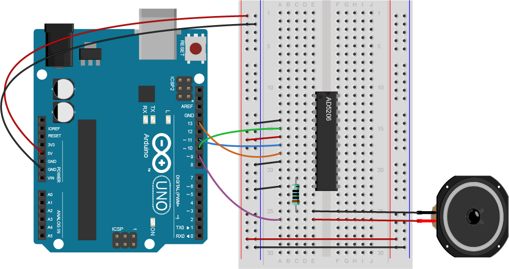
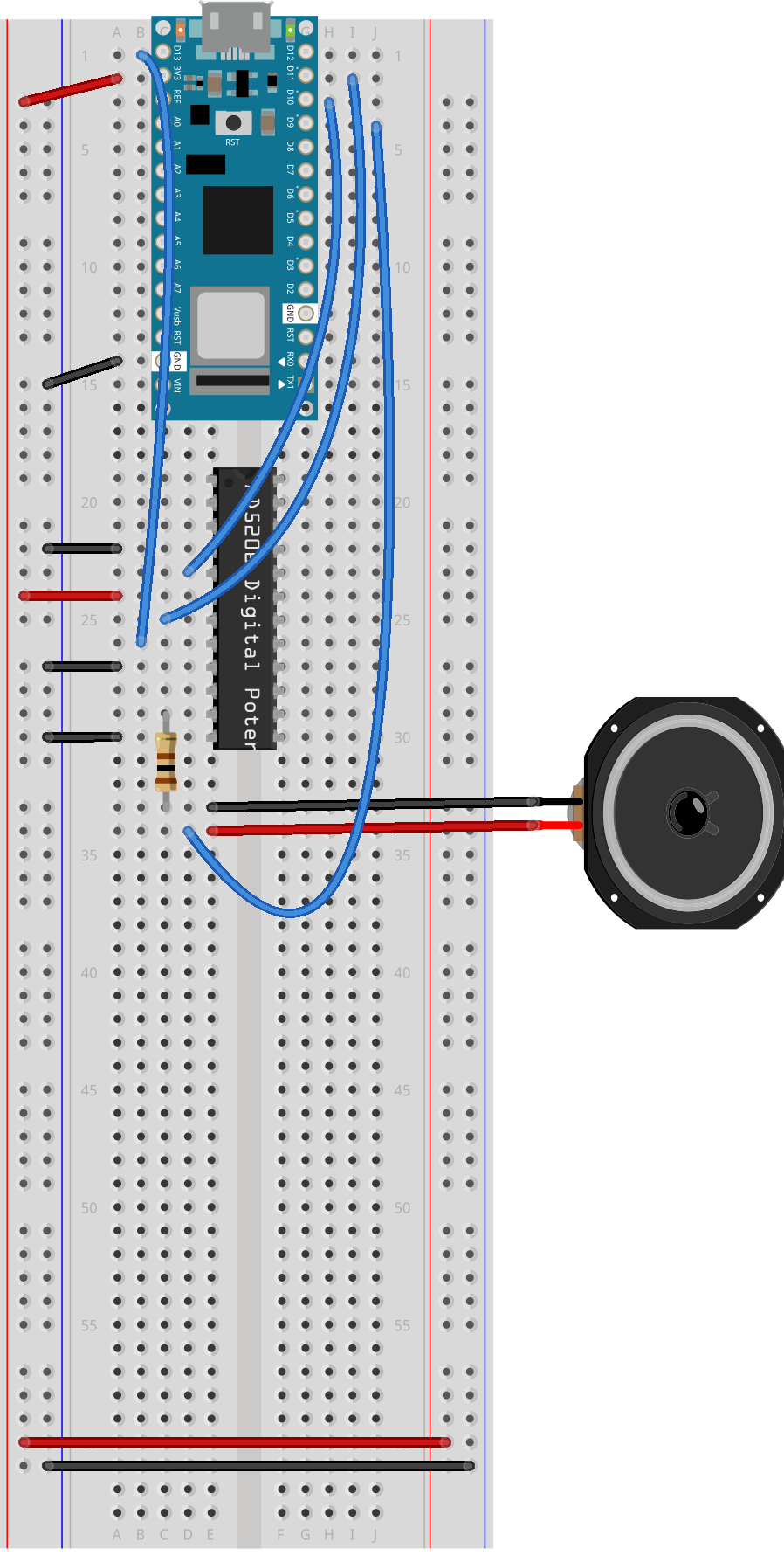
Figure 13. Schematic of an Arduino attached to a AD5206 Potentiometer and a speaker. The Arduino’s ground is attached the the potentiometer’s A5, Vss, and Ground pins, numbered 12, 9, and 4, respectively. The Arduino’s D10, D11, and D13 pins are attached to the potentiometer’s CS, SDI, and CLK pins, which are numbered 5, 7, and 8, respectively. The potentiometer’s Vdd pin, number 6, is connected to 3.3 volts. The Arduino’s D9 pin is connected to the negative terminal of a speaker. The speaker’s positive terminal is connected to a 100 Ohm resistor, which is connected to the potentiometer’s W5 pin, number 11.
Program the Microcontroller
The AD5206 has a simple command protocol, detailed in the “Operation” section of the data sheet. You send two bytes: the channel number you wish to control, and the level for the channel. Setting a channel to 0 makes the resistance between the wiper and the B pin 0 ohms, and setting it to 255 makes the resistance between the wiper and B 10 kilohms. There’s one slightly confusing issue: the channels are addressed as numbers 0 through 5 in code, yet numbered 1 through 6 on the pin diagram. Just remember that the first channel is channel 0, the second channel is channel 1, and so forth (just like array elements in most programming languages).
You can find Arduino-compatible libraries for many SPI devices that use the SPI library, but never expose it directly in the API. Instead, these libraries will include device-specific commands that use the SPI library to transfer data. Because the AD5206’s protocol is so simple, however, you don’t need a device-specific library, you can just use the SPI library. It’s a good illustration of what’s going on inside of some of the more complex SPI libraries.
At the beginning of your code, include the SPI library and set up a pin number for the chip select pin. The other SPI pins are set by the microcontroller you’re using (see the Arduino SPI reference page for the pin numbers). Then in the setup function, call SPI.begin() to initialize communications:
// include the SPI library:
#include "SPI.h"
const int CSPin = 10;   // chip select pin number

void setup() {
  // initialize SPI:
  SPI.begin();
  // set the mode of CSPin
  pinMode(CSPin, OUTPUT);
}
In your main loop, first make a tone on pin 9. Then make two for() loops to fade the loudness up and down. The actual work of controlling the digital potentiometer will be handled by a function you’ll write called digitalPotWrite():
void loop() {
tone(9, 440); // play a tone on pin 9

// fade the loudness up:
for (int loudness = 100; loudness <= 255; loudness++) {
digitalPotWrite(4, loudness);
delay(20);
}
delay(1000); // delay 1 second

// fade the loudness down:
for (int loudness = 255; loudness >= 100; loudness--) {
digitalPotWrite(4, loudness);
delay(20);
}

delay(1000); // delay 1 second
}
Finally, write the digitalPotWrite() function to control the digital potentiometer via SPI. Because SPI data can go both directions at the same time, i.e. from controller to peripheral and from peripheral to controller, there is a single command, SPI.transfer(), to transfer data instead of the read() and write() commands you’re used to from asynchronous serial communication. In order to put the digital pot in listening mode, you take its chip select pin low, then when you’re finished communicating with it, you take the pin high again:
void digitalPotWrite(int address, int value) {
  // take the SS pin low to select the chip:
  digitalWrite(CSPin, LOW);
  // send in the address and value via SPI:
  SPI.transfer(address);
  SPI.transfer(value);
  // take the SS pin high to de-select the chip:
  digitalWrite(CSPin, HIGH);
}
Once you upload this code, you’re done! You should hear the tone (middle A, 440Hz) fading in and out. You may have noticed that the for() loops fade from 100 to 255. The digital pot is changing the resistance across the wiper on the fifth potentiometer (aka channel 4) from approximately 3921 ohms (100/255 * 10k) to 10 kilohms. These are the levels that were determined from experiment to be the edges of audibility. But if your hearing is better, you may try adjusting the lower limit to see if you can hear it at a lower level.
Conclusion
This is a very simple use of SPI. Data only goes from controller peripheral in this example, and only two bytes are transferred. However, it gives you an indication of how the process works. Each SPI-based device will have its own command protocol, and data will be transferred from controller to peripheral (and vice versa) using the SPI transfer command. To open communications with a given SPI device, you take its chip select pin low, and to close communications, you take the chip select pin low again. This same procedure will work on all SPI devices once you know the command protocol. Keep in mind that most device-specific libraries will handle the SPI communication for you without you having to see it, just like the digitalPotWrite() command does in this example.
For another example of SPI in action with the AD5206, see the digital pot example on the Arduino site. There’s also an example with a barometric pressure sensor. The SD card library, which allows you to communicate with SD cards, uses the SPI library as well, and is used in the Data Logging with an SD card lab.