In this lab you’ll learn about sensor data logging and use SPI communication to write data to a microSD card from an Arduino.
Introduction
Sometimes you need to collect data with a microcontroller when there’s no way to communicate with another computer while you’re doing it. This is where removable storage like an SD card helps. In this lab, you’ll see how to use the Serial Peripheral Interface (SPI) protocol to write to an SD card. You’ll take sensor readings on a microcontroller and write them to a file on the SD card reader using the SPI protocol. You’ll also consider what it means to collect data about physical phenomena.
Related videos: Intro to Synchronous Serial, SPI
Data Collection and the Physical World
If you’re interested in data visualization and analysis, you have to start by gathering data, and much of that comes from physical activity. Though this lab doesn’t address the many non-technical considerations of data gathering, Mimi Onuoha’s essay The Point of Data Collection is an excellent introduction to that topic which you should also read when considering this lab.
Though this lab introduces you to the formatting and storage of sensor data on an SD card, there are multiple factors that you must consider in order to gather sensor-based data effectively, safely, and ethically. Here are just a few:
- the conditions which you want to observe,
- the sensors to use, and their sensitivity, resolution, and placement
- the circumstances in which you’re observing, and who will be affected by that observation and the data that results from it.
- the time scale of the observation, and the frequency of your readings
- the formatting of the data and and the capacity for storing it
- the energy needed to read the sensors and store the data
It’s not possible to address all of those issues in this lab, but many of them will be referenced along the way.
What You’ll Need to Know
To get the most out of this Lab, you should be familiar with the basics of programming an Arduino microcontroller. If you’re not, review the Digital Input and Output Lab, and perhaps the Getting Started with Arduino guide. You should also understand the basics of synchronous serial communication.
Things You’ll Need
Figure 1-5 show the components that you need for this lab.

Figure 1. 22AWG solid core hookup wires. 
Figure 2. Arduino Nano 33 IoT 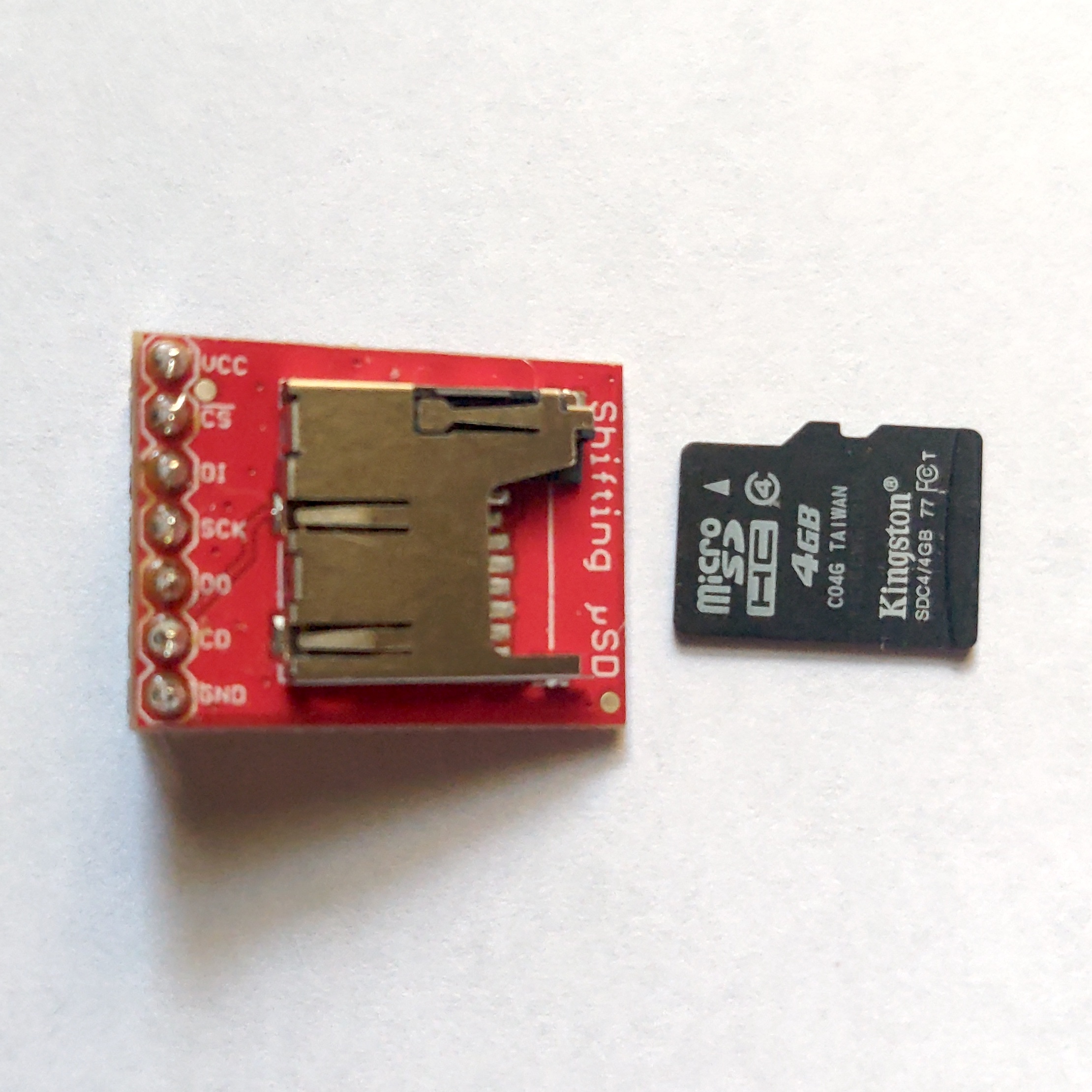
Figure 3. MicroSD card breakout board 
Figure 4. A short solderless breadboard. 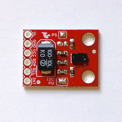
Figure 5. A sensor.
Connect a Sensor to a Microcontroller
The sensors you use will depend on the activity you’re planning to study. For this exercise, start with a sensor that you’ve already learned how to use. Connect connect the sensor to your microcontroller. It might be a digital or analog input. It might be OneWire, like the DHT11 or DHT22 temp/humidity sensors. It might be I2C, like the APDS-9960 light sensor shown in Figure 5 (and covered in this I2C lab), or the TMP007 temperature sensor (covered in this lab). It could be built into your microcontroller board, like the IMU sensor built into the Nano 33 IoT (and covered in this lab). It might be asynchronous serial, like a GPS receiver. Getting the sensor’s data into the microcontroller is up to you.
Verify that the sensor’s working with the microcontroller by getting an initial reading.
The code below uses a generic analog input as sensor, to simplify the code. Once you have this working, you should add the appropriate code to read your particular sensor.
Connect an SD Card Reader to the Microcontroller
SD cards use the Serial Peripheral Interface (SPI) protocol to communicate with microcontrollers and other computers. SPI is a synchronous serial protocol that supports two-way communication between a controller device such as a microcontroller and a peripheral device like an SD card reader. All SPI devices have a common set of connections:
- a Serial Data In (SDI) connection, on which the controller sends data to the peripheral devices.
- a Serial Data Out (SDO) connection, on which the peripheral devices send data to the controller.
- a Serial Clock (SCLK) connection, on which the controller sends a regular clock signal to the peripheral devices.
- one or more Chip Select (CS) connections, which the controller uses to signal the peripheral devices when to listen to incoming data and when to ignore it.
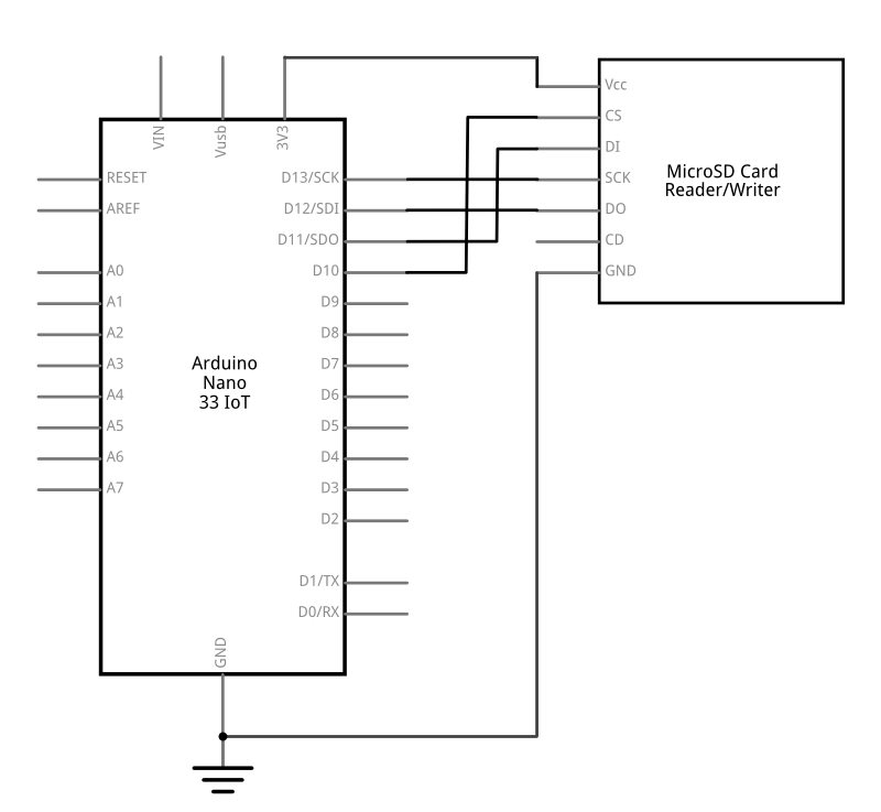
The SPI pin numbers are the same numbers for the Uno and Nano 33 IoT, as follows:
- SDO – pin 11
- SDI – pin 12
- SCK – pin 13
- CS – pin 10
If you’re using a MKRZero, it has a built-in SD card and a built-in SD card chip select called SDCARD_SS_PIN.
The MicroSD card reader/writer shown in Figures 3, 7, and 8 is from Sparkfun, and has level-shifting circuitry built-in to adjust for either 3.3- or 5-volt operation. There are many other models on the market though. Here’s an Adafruit model. Here’s a Pololu model. Here’s a DFRobot model. All of them will communicate with your microcontroller in basically the same way, though, using the SPI pin connections.
Most SD card readers have a card detect (CD) pin as well, that changes state when the card is inserted or removed. It’s optional, but it can be useful to make sure you have a card in the reader.
Connect your Arduino to the SD card reader as shown in Figure 6 and 7. If you’re using the Sparkfun SD card reader/writer, the pins are on the on the left side of the board, and they’re numbered, from top to bottom, as follows:
- Vcc – voltage in. Connects to microcontroller voltage out
- CS – Chip select. Connects to microcontroller CS
- DI – SPI data in. Connects to microcontroller SDO
- SCK – SPI clock.. Connects to microcontroller SCLK
- DO – SPI data out.. Connects to microcontroller SDI
- CD – card detect. Connects to microcontroller pin 9
- GND – ground. Connects to microcontroller ground

Format the SD Card
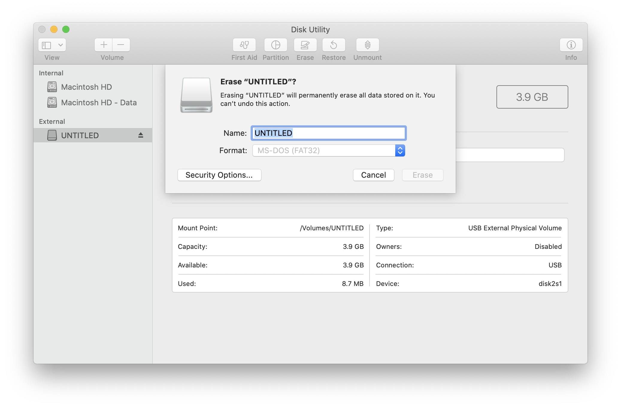
Different operating systems use different file formats. Your SD card needs to be formatted as FAT16 or FAT32 in order to work with the SD card library. This format is common on Windows and Linux, but not always on MacOS computers. There are some notes on formatting on the Arduino SD Card library reference.
Formatting an SD Card (Windows)
On Windows, right-click the disk and choose “Format…” The fedault formatting option is FAT32, which will work for this lab.
Formatting an SD Card (MacOS)
You can format a card as FAT32 using the MacOS Disk Utility application by selecting the SD card, Clicking the Erase button or typing command-shift-E, then selecting MS-DOS (FAT) from the Format Option menu that appears in the Format dialog. Figure 8 shows a screenshot of the MacOS Disk Utility application.
Import the SD Library
With most SPI devices, you generally won’t write your own SPI commands. Most every company that makes a breakout board for a given SPI device will also write a library for it. The device-specific library abstracts away the process of using the SPI commands for the device.
Since SD card formats are a known standard, the SD card library for Arduino works with multiple different card readers, and was contributed to by authors from multiple companies. The library comes with several useful example programs to test your card reader and your card. Once you’ve installed the library from the Library Manager, you can find these examples if you click the File menu, examples submenu, then the SD submenu.
Test the SD card Reading and Writing
The CardInfo sketch will read the SD card and print out its formatting info and a list of files. This is a good place to start, to see if you formatted the card correctly. The Files example will read the card and check for a file called example.txt on the card. ListFiles will print a list of the card’s file directory. With any of these, make sure to change the chipSelect pin number to the same pin as your board. If all of those work, you’re ready to write your sketch. There’s one in the library examples, but the code below walks you through the steps of writing your own.
A Datalogger Sketch
The first thing you need to do in your sketch is to include the SD card library at the top. The library includes a File class, which you can read to and write from like a file. Make an instance of that class, and make a constant for the file name. Make the file type .csv (comma-separated values) so the file is easy to read with a spreadsheet application later. Add constants for the chip select and card detect pins as well, and a variable to keep track of when your last successful reading was logged to the card:
// the SPI CS pin
const int chipSelect = 10;
const int cardDetect = 9;
// the filename. Use CSV so the result can be opened in a spreadsheet
const char fileName[] = "datalog.csv";
// time of last reading, in ms:
long lastReading = 0;
The File class implements many of the same functions as the Serial class that you’re already familiar with, like read(), write(), print(), println(), and available(). Both File and Serial are instances of a data class called a Stream. You’ll see other examples of Stream in other libraries for communication, like I2C and WiFi.
This sketch won’t use the Serial Monitor, since you won’t be attached to a computer when you’re reading data. Instead, you’ll use the built-in LED to tell whether things are working or not.
Detect and Initialize the Card
In the setup(), initialize the LED, and use the card detect pin to tell if there’s a card present or not. When it’s there, use the SD.begin() to attempt to initialize the card. The SD.begin() function’s parameter is the chip select pin number.
void setup() {
  // variable for the LED's state:
  int ledState = HIGH;
  pinMode(LED_BUILTIN, OUTPUT);
  pinMode(cardDetect, INPUT);

  // if the card detect pin is false, no card:
  while (digitalRead(cardDetect) == LOW) {
    // toggle LED every 1/4 second while the SD card's not present:
    digitalWrite(LED_BUILTIN, HIGH);
  }
  // give the reader 5 seconds to settle the card once it's detected:
  delay(5000);

  // if the card is not present or cannot be initialized:
  while (!SD.begin(chipSelect)) {
    // toggle LED every 1/4 second while the SD card's not responding:
    digitalWrite(LED_BUILTIN, ledState);
    // change the LED state:
    ledState = !ledState;
    delay(250);
  }
  // turn the LED off:
  digitalWrite(LED_BUILTIN, LOW);
}
Set the Reading Interval
Start the main loop() function by checking the millis() function to see if one second (1000 ms) have passed since your last successful reading. Later in the code, you’ll update the lastReading variable using the millis() function:
void loop() {
  // read once a second:
  if (millis() - lastReading > 1000) {
Read the Sensors and Format for Writing
Next, set up a String variable, and use it to collect your sensor readings and any formatting, like the commas that will separate the readings. Then read your sensors and add them to the String:
    // make a string for assembling the data to log:
    String dataString = "";

    // read your sensors:
    int sensorOne = analogRead(A0);
    dataString += String(sensorOne);
    delay(1);
    // comma-separate the values:
    dataString += String(",");
    int sensorTwo = analogRead(A1);
    dataString += String(sensorTwo);
Write to the File
Once you’ve got the data formatted, check to see if you can open the File you created on the SD card for writing. If you can, then write to it. Turn the LED on when you’re writing, and off when you’re not, so you know when the card is busy. When you turn the LED off, update the lastReading variable with the time fron millis(). If you can’t access the file, turn the LED on constantly to indicate that there’s a problem. After that, you can close the initial if() statement that checks the time, and close the main loop:
    // open the file. Only one file can be open at a time,
    // so you have to close this one before opening another.
    File dataFile = SD.open(fileName, FILE_WRITE);

    // if the file is available, write to it:
    // turn the LED on while writing and off when not writing too:
    if (dataFile) {
      digitalWrite(LED_BUILTIN, HIGH);
      dataFile.println(dataString);
      dataFile.close();
      digitalWrite(LED_BUILTIN, LOW);
      lastReading = millis();
    } else {
      // if the file can't be opened, leave the LED on:
      digitalWrite(LED_BUILTIN, HIGH);
    }
  } // end of if millis() statement
} // end of loop
the dataFile.close() function is the one that actually stores the data to the card, so when that’s done, you know the data should be on the SD card. If you don’t want to open and close a lot, you can also use the dataFile.flush() function to write to the card.
That’s the whole working sketch. Try it. Once it’s run for a minute or so, remove the SD card, put it in your computer and see if there’s a file called datalog.csv on it. Open the card in a spreadsheet program to see your data.
You can find versions of this for the Nano 33 IoT’s built in IMU, for the APDS-9960 color sensor, and for the DHT11/DHT22 temperature and humidity sensors in the repository for this site.
Decide How and When to Record Data
Even though your sensor might be able to deliver multiple readings a second, you have to decide how frequently you need to record the results. For example, if you’re measuring temperature change in a room, do you need to read more frequently than once a minute?
How you format the data for storage and how frequently you read it affects how much memory it takes. For example, imagine you’re reading a temperature sensor and storing the results as a string, like so:
21.45°C
Each character of that reading takes a byte of data. So each reading would take about 6 to 8 bytes, depending on how many digits are involved, and whether you use a label like “°C” or not. If you’re reading from multiple sensors, or adding a time stamp to each reading, each reading can easily take 10 to 20 bytes or more.
Now, imagine you plan to store readings ten times a second. For every second, that’s 100 bytes. For every minute, 6 kilobytes. For every hour, 360 kilobytes. For every day, 8.6 megabytes.
Each reading takes energy as well. Different sensors draw differing amounts of current, as does an SD card reader. To find out how much, you could program your microcontroller to write once a second, and then measure the current over several seconds to see the differences in current draw when it’s measuring and when it’s not.
Given all of that, how frequently should you read your sensors? It depends on the activity. If you’re trying to record a hand or arm gesture using an an IMU sensor, you should read multiple times a second, because even a tenth of a second can change where the limb you’re measuring is. If you’re recording the change in air quality in your home, the air probably doesn’t move that fast, so once a minute, or even less, might be fine. Before you can build the circuit or write any code, you should make these decisions, to simplify the development of your device.
Time Stamp the Data
In order to see how the data changes over time, you need to keep track of when each reading was recorded. For many short-term datalogging experiments, you can simply use the millis(), or divide the millis() by 1000 to get seconds. That method loses a few seconds every day, but it’s fine if you’re logging data only for a few minutes or an hour or so. If you’re recording for longer or you need precise time of day and you are using a MKR board or the Nano 33 IoT, you can use the real-time clock that’s built into it, using the RTCZero library. A real-time clock (RTC) is an electronic component that keeps accurate time, usually attached to a microcontroller via synchronous serial communications protocols like I2C or SPI. The SAMD21 processor that’s at the heart of the MKR boards and the Nano 33 IoT has a built-in RTC. Here’s a lab that explains how to do that.
Conduct the Measurements
Once you’ve gotten your code and circuit working, it’s time to take some readings. Place the sensor where it can read the activity you want to read, and let it run for a short interval. If it’s not supposed to be sensing your activity, leave it alone while it’s doing its job. Then turn it off, remove the SD card, and read the data on your personal computer. Once you’re confident that your device is working as you intended it, you can set it up to run for a longer time.
Review the Data
Since you saved the file as a .csv file, it will most likely open up in your favorite spreadsheet application, and you can see the results in a table. This can be very handy for looking through the data in a systematic way. You can then sort it by highest value, or by time (it should already be sorted by time), or if you are using multiple sensors, you can sort by one sensor value or the other.
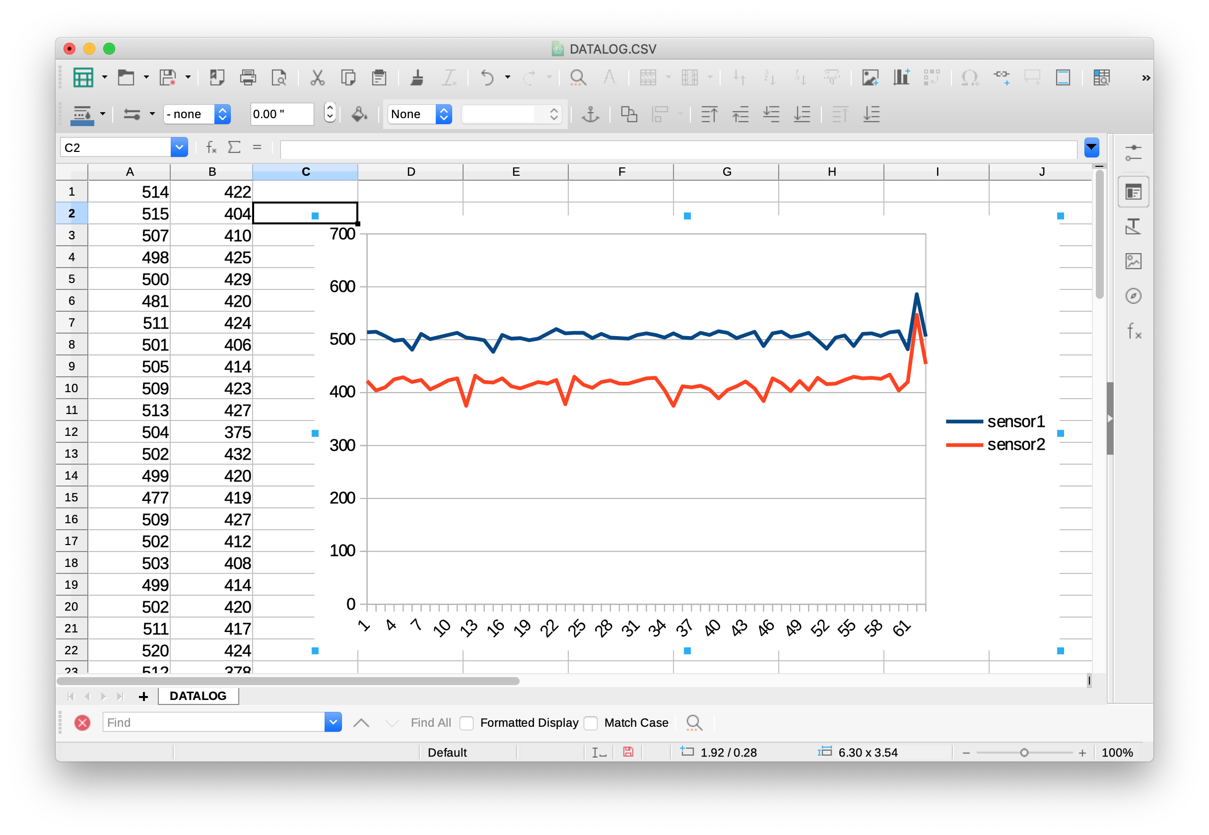
Visualize the Data
The other advantage of using a spreadsheet program is that most all of them have a graphing tool built in that will allow you to graph the results of your sensor readings, as shown in Figure 9. With a graph, you can look for patterns in the changes of data visually. Of course, you could write your own graphing program in p5.js or Processing or some other program, but by using a standard data format (CSV), and writing to a file on an SD card, you’ve made it possible to use existing software tools to analyze the data from your sensors.
Powering the Datalogger for Long-Term Measurements
If you’re setting up an environmental sensor, or a sensor to read the changes in a space over a long time, you’ll need a way to power your device. If there’s electrical power, you could simply plug the device into the wall using a USB adapter. If you can’t plug into the wall, you’ll need a battery. For some background on voltage and power, view this video on electrical power.
Battery Capacity
Batteries are rated by voltage and energy capacity. Capacity is usually given in milliamp-hours. You might think that if a battery is a 2000mAh (2000 milliamp-hours), the battery can supply a maximum of 2000 milliamps at a given instant when it’s charged, and can do so for up to one hour. That’s not the whole story though. Batteries don’t charge or discharge in a linear fashion, though. Maximum charging and discharging rates are relative to a battery’s total capacity; in other words, larger batteries can both supply higher currents, and charge at higher currents.
Batteries are tested at a “C-rate”, which you can find in their data sheet, that actually determines the maximum current that a batterycan supply. A 1000 mAh battery could provide more than 1 amp depending on it’s maximum discharge C-rating. If the rate is 2C, then the battery could provide 2 amps (for less than the full hour, of course). For example, here’s a 2000 mAh battery from Adafruit. This battery’s data sheet indicates that its performance was rated at 0.2C, indicating that though it’s rated for 2000 mAh, its standard charging and discharge current is 0.5 amps.
Mobile phone charging battery packs can be convenient because they already have a USB plug on them. It’s easy to find packs that have a capacity of 1000 mAh or more at 5 volts. A variety of standard battery combinations can work, like a 9V battery or a set of AA cells in a battery clip. AA batteries are typically 1.5V each, so you’d need a 3- or 4-battery clip to get enough voltage to run your processor.
Rechargeable 3.7V lithium polymer batteries are available too (also called Lithium-ion, Li-Ion, LiPoly, or LiPo), and can run the Nano 33 boards, though usually not an Uno. These are useful because you can reuse them many times, unlike other batteries. These are often found inside the mobile phone chargers mentioned earlier (and in mobile devices and laptops). Here are some examples:
Make sure to check the connector type on your Li-ion batteries. The most common connector is a 2-pin JST-PH connector, but some manufacturers use variations on this. Also check the polarity, as sometimes they come wired backwards. Connecting a battery to a charger backwards can damage both.
With these, you’ll need a charger. There’s one built into the MKR boards, and there are number of charger options. Here are a few:
- Adafruit Micro USB Li-Ion/LiPoly Charger
- Adafruit USB Li-Ion/LiPoly Charger – V1.2
- SparkFun LiPo Charger Basic – Micro-USB
- Sparkfun LilyPad Simple Power
- DFRobot Lipo Charger-MicroUSB
Only charge lithium batteries with a dedicated charger designed for the specific type and number of cells you are using! The Adafruit chargers, for example, can only charge 1-cell batteries with 3.7V/4.2V cells. A rechargeable battery must be charged at a specific safe charging rate,. All batteries are potentially explosive if mis-handled or misused in charging and discharging, and lithium batteries can be particularly volatile, as this animation of a man biting a battery like an old-timey prospector biting a gold coin shows.
Put Your Microcontroller to Sleep When it’s not Reading
Your device consumes power when even when it’s not running, and when you’re running on battery power, that means you can log less data before the battery dies. One way to get more readings out of a battery is to put the microcontroller to sleep. Different microcontrollers have different modes of sleep that they can use. The Uno, unfortunately, has no easy sleep mode, but the Nano 33 IoT and MKR boards do, using the ArduinoLowPower library. With this library, you can put the microcontroller into a number of low power modes, and wake it up, either after a set time using the real time clock, or from a change on input pin (called an external interrupt):
- Idle – this mode has the fastest wake-up time, but the least power savings. The processor is stopped, but peripherals like the realtime clock (RTC), analog-to-digital converter (ADC) and Serial, and I2C are not.
- Sleep – this mode allows has slower wakeup time, but better power savings. Only the peripherals you’re using in your sketch remain on.
- Deep sleep – This mode has the the slowest wake-up time and the best power savings. All but the realtime clock peripherals are stopped. The CPU can be woken up only using the clock or interrupt pins.
Conclusion
Though this lab is primarily about connecting an SD card reader to a microcontroller to write sensor-based data to an SD card, this exercise has lots of secondary factors which you need to consider, from the energy needed to gather the data to the design of the data-gathering experiment to the individuals whose activities are represented in the data. All of these come into play even before you consider how to present the data that you’ve gathered. Hopefully this introduction has given you a starting place from which to consider those factors.