Introduction
In this exercise you’ll read the built-in Inertial Motion Unit on the Arduino Nano 33 IoT, then feed its output into a Madgwick filter to determine heading, pitch, and roll of the board. Then you’ll send the output of that serially to p5.js and use it to move a virtual version of the Nano onscreen.
What You’ll Need to Know
To get the most out of this lab, you should be familiar with the following concepts and you should install the Arduino IDE on your computer. You can check how to do so in the links below:
- What is a microcontroller
- Beginning programming terms
- The basics of electricity
- What is a solderless breadboard and how to use one
- Getting Started with Arduino Guide
- The basics of serial communication, both asynchronous and synchronous.
- Two-Way (Duplex) Serial Communication Using An Arduino and the p5.webserial Library
- The basics of accelerometers, gyrometers, and IMUs
Things You’ll Need
The only part you’ll need for this exercise is an Arduino Nano 33 IoT and its built-in IMU, as shown in Figure 1. You can modify this exercise to work with other IMUs, however. There are details on various IMUs on the accelerometers, gyrometers, and IMUs page.

Prepare the Breadboard
because the Nano 33 IoT has a built-in IMU, there is no additional circuit needed for this exercise. However, there are two libraries you’ll need to install: the Arduino_LSM6DS3 library, which allows you to read the IMU, and the MadgwickAHRS library, which takes the raw accelerometer and gyrometer inputs and provides heading, pitch, and roll outputs. Both libraries can be found in the Library Manager of the Arduino IDE. Install them before proceeding.
Program the Microcontroller to Read the IMU
The first thing to do in the microcontroller code is to confirm that your accelerometer and gyrometer are working. Start with the code below:
#include "Arduino_LSM6DS3.h"

void setup() {
  Serial.begin(9600);
  // attempt to start the IMU:
  if (!IMU.begin()) {
    Serial.println("Failed to initialize IMU");
    // stop here if you can't access the IMU:
    while (true);
  }
}

void loop() {
  // values for acceleration and rotation:
  float xAcc, yAcc, zAcc;
  float xGyro, yGyro, zGyro;

  // check if the IMU is ready to read:
  if (IMU.accelerationAvailable() && IMU.gyroscopeAvailable()) {
    // read accelerometer and gyrometer:
    IMU.readAcceleration(xAcc, yAcc, zAcc);
    IMU.readGyroscope(xGyro, yGyro, zGyro);

    Serial.print("sensors: ");
    Serial.print(xAcc);
    Serial.print(",");
    Serial.print(yAcc);
    Serial.print(",");
    Serial.print(zAcc);
    Serial.print(",");
    Serial.print(xGyro);
    Serial.print(",");
    Serial.print(yGyro);
    Serial.print(",");
    Serial.println(zGyro);
  }
}
When you run this sketch and open the Serial Monitor, you should see a printout with six values per line. The first three are your accelerometer values, and the next three are your gyrometer values. The following reading is typical:
sensors: 0.04,-0.05,1.02,3.05,-3.72,-1.77
The Nano 33 IoT’s accelerometer’s range is fixed at +/-4G by this library, and its gyrometer’s range is set at +/-2000 degrees per second (dps). The sampling rate for both is set to 104 Hz by the library. Other IMUs may have differing ranges. You need to know at least the sampling rate when you want to use a different IMU with this exercise. If you know that information, though, it’s easy to swap one IMU for another in the Madgwick library.
Add the Madgwick Library to Get Orientation
The MadgwickAHRS library can work with any accelerometer/gyrometer combination. It expects the acceleration in Gs and the rotation in degrees per second as input, and uses the sensors’ sampling rate when you initialize it. Add a few lines to the code before your setup() as follows:
#include "Arduino_LSM6DS3.h"
#include "MadgwickAHRS.h"

// initialize a Madgwick filter:
Madgwick filter;
// sensor's sample rate is fixed at 104 Hz:
const float sensorRate = 104.00;

// values for orientation:
float roll = 0.0;
float pitch = 0.0;
float heading = 0.0;
Next, add the following line at the end of the setup() to initialize the Madgwick filter:
// start the filter to run at the sample rate:
filter.begin(sensorRate);
Now change the main loop so that you’re sending the sensor readings into the Madgwick filter. You’ll do this inside of the if statement that checks if the sensors are ready:
// check if the IMU is ready to read:
if (IMU.accelerationAvailable() &&
IMU.gyroscopeAvailable()) {
  // read accelerometer and gyrometer:
  IMU.readAcceleration(xAcc, yAcc, zAcc);
  IMU.readGyroscope(xGyro, yGyro, zGyro);

  // update the filter, which computes orientation:
  filter.updateIMU(xGyro, yGyro, zGyro, xAcc, yAcc, zAcc);

  // print the heading, pitch and roll
  roll = filter.getRoll();
  pitch = filter.getPitch();
  heading = filter.getYaw();

  // print the filter's results:
  Serial.print(heading);
  Serial.print(",");
  Serial.print(pitch);
  Serial.print(",");
  Serial.println(roll);
}
Now when you run the sketch, you’ll get heading, pitch, and roll instead of the raw sensor readings. Here’s a typical output you might see:
167.59,-2.50,-2.52In this case, the readings are all in degrees. The first is the heading angle, around the Z axis. The second two are the pitch, around the x axis, and roll, around the Y axis.
Add Serial Handshaking
Reading these values in p5.js will work smoother if you add handshaking, also known as call-and-response, to your serial communications protocol. Modify the loop() so that the sketch sends the latest heading, pitch, and roll whenever a new byte comes in the serial port. Here’s the final version of the loop():
void loop() {
  // values for acceleration and rotation:
  float xAcc, yAcc, zAcc;
  float xGyro, yGyro, zGyro;

  // check if the IMU is ready to read:
  if (IMU.accelerationAvailable() & amp; & amp;
      IMU.gyroscopeAvailable()) {
    // read accelerometer and gyrometer:
    IMU.readAcceleration(xAcc, yAcc, zAcc);
    IMU.readGyroscope(xGyro, yGyro, zGyro);

    // update the filter, which computes orientation:
    filter.updateIMU(xGyro, yGyro, zGyro, xAcc, yAcc, zAcc);

    // print the heading, pitch and roll
    roll = filter.getRoll();
    pitch = filter.getPitch();
    heading = filter.getYaw();
  }

  // if you get a byte in the serial port,
  // send the latest heading, pitch, and roll:
  if (Serial.available()) {
    char input = Serial.read();
    Serial.print(heading);
    Serial.print(",");
    Serial.print(pitch);
    Serial.print(",");
    Serial.println(roll);
  }
}
this link. When you have this much working, and you’ve tested it in the Serial Monitor, you can close Arduino and work on the p5.js sketch.
Program p5.js to Read the Incoming Serial Data
Now it’s time to write a p5.js sketch to read this data. The setup will be the same as it was in the Serial Input to p5.js using WebSerial lab. The checklist from that lab lays out all the important parts you need.
Make a P5.js sketch. If you’re using the p5.js web editor, make a new sketch. Click the Sketch Files tab, and then choose the index.html file. Edit the head of the document as you did for the other p5.webserial labs. It should look like this:
<script src="https://cdnjs.cloudflare.com/ajax/libs/p5.js/1.4.0/p5.js"></script>

<script src="https://unpkg.com/p5-webserial@0.1.1/build/p5.webserial.js"></script>
Start your sketch with some code to initialize the serial library:
// variable to hold an instance of the p5.webserial library:
const serial = new p5.WebSerial();

// HTML button object:
let portButton;

function setup() {
  	createCanvas(500, 600, WEBGL);     // make the canvas
  // check to see if serial is available:
  if (!navigator.serial) {
    alert("WebSerial is not supported in this browser. Try Chrome or MS Edge.");
  }
  // if serial is available, add connect/disconnect listeners:
  navigator.serial.addEventListener("connect", portConnect);
  navigator.serial.addEventListener("disconnect", portDisconnect);
  // check for any ports that are available:
  serial.getPorts();
  // if there's no port chosen, choose one:
  serial.on("noport", makePortButton);
  // open whatever port is available:
  serial.on("portavailable", openPort);
  // handle serial errors:
  serial.on("requesterror", portError);
  // handle any incoming serial data:
  serial.on("data", serialEvent);
  serial.on("close", makePortButton);
}
function draw() {

}

// if there's no port selected,
// make a port select button appear:
function makePortButton() {
  // create and position a port chooser button:
  portButton = createButton('choose port');
  portButton.position(10, 10);
  // give the port button a mousepressed handler:
  portButton.mousePressed(choosePort);
}

// make the port selector window appear:
function choosePort() {
  serial.requestPort();
}

// open the selected port, and make the port
// button invisible:
function openPort() {
  // wait for the serial.open promise to return,
  // then call the initiateSerial function
  serial.open().then(initiateSerial);

  // once the port opens, let the user know:
  function initiateSerial() {
    console.log("port open");
    serial.write("x");
  }
  // hide the port button once a port is chosen:
  if (portButton) portButton.hide();
}

// read any incoming data:
function serialEvent() {
  // read a string from the serial port
  // until you get carriage return and newline:
  var inString = serial.readStringUntil("\r\n");
  console.log(inString);
}

// pop up an alert if there's a port error:
function portError(err) {
  alert("Serial port error: " + err);
}

// try to connect if a new serial port
// gets added (i.e. plugged in via USB):
function portConnect() {
  console.log("port connected");
  serial.getPorts();
}

// if a port is disconnected:
function portDisconnect() {
  serial.close();
  console.log("port disconnected");
}
Save this as sketch.js, then open p5.serialcontrol. Then open the sketch in a browser. Open the JavaScript console, and you should see the first set of data printed out. This is because the initiateSerial() function sent a single byte to the Nano when the port opened, and the Nano sent one set of readings. That generated a serial data event in p5.js, and called the serialEvent() function, which printed out the results.You need this to happen repeatedly: p5.js sends a byte when it wants new data, then the Nano sends the data, then waits for another byte from p5.js.
Add Serial Handshaking
To make this happen, you need to add a few things to your p5.js sketch. You can assume that if you saw the message in the console, then you’re ready for new data. That’s when you should send a byte back to the microcontroller to request new data. Add one line to the serialEvent() function to make this happen:
// callback function for incoming serial data:
ffunction serialEvent() {
  // read a string from the serial port
  // until you get carriage return and newline:
  var inString = serial.readStringUntil("\r\n");
  if (inString != null) {
    console.log(inString);
    serial.write("x");
  }
}
When you run the sketch with this update, you should see a continuous flow of new data from the microcontroller.
Next, you need to break the string up into parts and convert them into floating point numbers so you can use them as heading, pitch, and roll. Start by adding three new variables at the top of your sketch as global variables, because you’ll need them when you draw the virtual Arduino:
// orientation variables:
let heading = 0.0;
let pitch = 0.0;
let roll = 0.0;
Next, in the serialEvent() function, use the JavaScript trim() function to get rid of any extraneous characters at the end of the message string, like carriage returns or newlines. Then use the split() function to split the string into a list of elements separated by commas. Then convert them to floating point numbers. Once you know you have three valid numbers for heading, pitch, and roll, send another byte to the microcontroller to get a new reading. Here’s what the new version of serialEvent() looks like:
function serialEvent() {
  // read from port until new line:
  let inString = serial.readStringUntil("\r\n");
  if (inString != null) {
    let list = split(trim(inString), ",");
    if (list.length > 2) {
      // conver list items to floats:
      heading = float(list[0]);
      pitch = float(list[2]);
      roll = float(list[1]);
      console.log(heading + "," + pitch + "," + roll);
      // send a byte to the microcontroller to get new data:
      serial.write("x");
    }
  }
}
When you reload the sketch after making these changes, you should be getting floating point numbers for heading, pitch and roll. Once you have these values coming in consistently, it’s a good idea to comment out the console.log() statement, as shown above, as it slows down the sketch considerably.
Now that you have serial communication working properly, it’s time to write the code to draw the virtual microcontroller.
Draw the Virtual Arduino
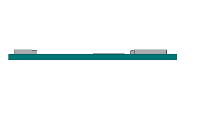
Add the function below to draw a virtual Arduino. It draws in three dimensions, using the WEBGL framework you chose in createCanvas() above in the setup() function.
// draws the Arduino Nano:
function drawArduino() {
   // the base board:
   stroke(0, 90, 90); // set outline color to darker teal
   fill(0, 130, 130); // set fill color to lighter teal
   box(300, 10, 120); // draw Arduino board base shape

   // the CPU:
   stroke(0);         // set outline color to black
   fill(80);          // set fill color to dark grey
   translate(30, -6, 0); // move to correct position
   box(60, 0, 60);    // draw box

   // the radio module:
   stroke(80);       // set outline color to grey
   fill(180);        // set fill color to light grey
   translate(80, 0, 0); // move to correct position
   box(60, 15, 60);  // draw box

   // the USB connector:
   translate(-245, 0, 0); // move to correct position
   box(35, 15, 40);	  // draw box
}
You haven’t added a draw() function yet, so add it now, as follows:
function draw() {
   background(255); // set background to white
   push();          // begin object to draw
   // draw arduino board:
   drawArduino();
   pop();           // end of object
}
When you reload the sketch, you’ll see a drawing like that in Figure 4. It won’t change.
To make it change its orientation, you need to use the heading, pitch, and roll values to rotate the object. You get the sine and cosine of each angle, and use them to generate a matrix for translation. The math below was worked out by Helena Bisby based on the Madgwick algorithm. p5.js’ applyMatrix() function does the matrix math for you to rotate in all three dimensions. Modify the draw() function as shown below:
function draw() {
   // update the drawing:
   background(255); // set background to white
   push();          // begin object to draw

   // variables for matrix translation:
   let c1 = cos(radians(roll));
   let s1 = sin(radians(roll));
   let c2 = cos(radians(pitch));
   let s2 = sin(radians(pitch));
   let c3 = cos(radians(heading));
   let s3 = sin(radians(heading));
   applyMatrix(c2 * c3, s1 * s3 + c1 * c3 * s2,
      c3 * s1 * s2 - c1 * s3, 0, -s2, c1 * c2,
      c2 * s1, 0, c2 * s3, c1 * s2 * s3 - c3 * s1,
      c1 * c3 + s1 * s2 * s3, 0, 0, 0, 0, 1);

   // draw arduino board:
   drawArduino();
   pop(); // end of object
}
When you reload the sketch after making these changes, the virtual Arduino should change its position as you move the physical Arduino. That’s the whole application! Figure 5 shows the virtual Arduino in motion.
You can see the sketch running on GitHub at this link. You can see the source files for copying into the p5.js editor at this link.
Conclusion
If you followed along all of the steps to this application, you probably hit a number of places where communication broke down. There are a lot of pieces to this application, and they all need to work together.
Get the Sensors Working
When you’re dealing with IMU sensors, no data will be perfect, because the sensor’s measurement is always relative. You’ll notice, for example, that the position of the virtual Arduino drifts a bit the longer you run the sketch. Heading, in particular, tends to drift. In real-world applications, this is often adjusted by using a magnetometer as a compass in addition to the accelerometer and gyrometer. It’s also wise to provide ways for a human to calibrate the system, perhaps by pressing a button when the sensor is level in order to calculate offset values for the sensors. For many interactive applications, though, even an imperfect measurement of orientation will do the job well.
Test the Hardware
If you’re using serial communication that’s ASCII-encoded like this, you can always use the Serial Monitor or another serial terminal application to test the Arduino sketch before you ever begin working on the multimedia programming. Ideally, you don’t need to change the Arduino sketch at all once your communication is working as planned.
Get the Communication Working
Whenever you’re building an application that incorporates asynchronous serial communication, it’s best to get the communication working correctly before you build the animation or other parts of the interaction. Once the communication protocol is known, you can even divide the work, with one team developing the hardware and another developing the media programming.
This exercise shows the value of using handshaking (aka call-and-response) in serial communication. Because the drawing of the microcontroller takes time, the p5.js sketch reads data less frequently than the microcontroller can send it. If you simply allow the microcontroller to send data continuously, the serial buffer on the p5.js side will fill up, and the movement of the virtual Arduino will become sluggish. This is why you only send back to the microcontroller when you know you have a set of valid data, in the serialEvent() function.
Test the Incoming Data
You don’t need to do anything with your incoming serial data to know it’s valid, if you’ve thought through the protocol well. In this case, if you see you’re getting three separate values and they’re all in a range of 0 to 360 (indicating degrees of the heading, pitch, and roll angles), you know it’ll work.
Program the Interface, Animation, etc.
Once you know the communication is good, and you’re getting accurate values, you can program the parts of your final application that use that data. In this case, you didn’t even start on the movement of the virtual Arduino until you knew you had communication working. Drawing of the virtual model was separated from moving it, using the push(), pop(), and translation functions, like applyMatrix(), in p5.js. That separation makes the programming easier to do, and easier to debug.