Introduction
In this lab, you’ll see synchronous serial communication in action using the Inter-integrated Circuit (I2C) protocol with a time-of-flight distance sensor and a microcontroller.
Many different sensors on the market use the I2C protocol to communicate with microcontrollers. It is the most common way to connect to advanced sensors these days. The VL53L0X used in this lab is typical of an I2C sensor, so the principles covered here will help you when working with other I2C sensors as well. Much of this lab is adapted from the I2C lab on the APDS-9960 Color, Light, and Gesture Sensor.
Related videos: Intro to Synchronous Serial, I2C
What You’ll Need to Know
To get the most out of this Lab, you should be familiar with the basics of programming an Arduino microcontroller. If you’re not, review the Digital Input and Output Lab, and perhaps the Getting Started with Arduino guide. You should also understand asynchronous serial communication and how it differs from synchronous serial communication. You should also read the notes on distance sensors to learn more about time-of-flight, or VCSEL sensors.
Things You’ll Need
Figure 1-3 are the parts that you need for this lab.


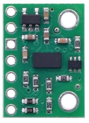
Sensor Characteristics
The sensor used in this lab, an ST Micro VL53L0X sensor, is an integrated circuit (IC) that can read the distance out to about 2000mm. It uses a 940 nm VCSEL emitter (Vertical Cavity Surface-Emitting Laser) that reflects off the target to determine the distance. There are breakout boards available for this sensor from multiple vendors, including Adafruit and Pololu (all available through Digikey, among others) .
I2C Connections
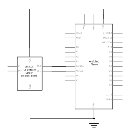
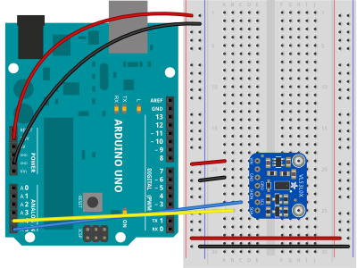
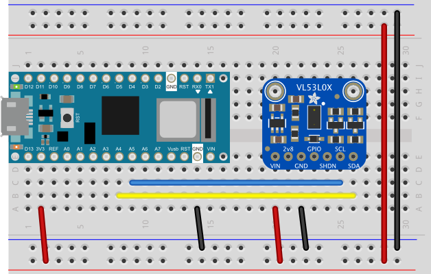
Connect the sensor’s voltage and ground pins to your voltage and ground buses, and the I2C clock (SCL) and I2C serial data (SDA) pins to your microcontroller’s corresponding I2C pins as shown in Figure 4-6. The schematic, Figure 4, is the same for both the Uno and the Nano. For the Arduino Uno or the Arduino Nano boards, the I2C pins are pins A4 (SDA) and A5(SCL). This is the same connection for almost any I2C sensor.
Some I2C sensors also have a few other pins:
- an interrupt pin, used to signal the microprocessor when a reading is ready.
- a shutdown or reset pin, used for powering down or resetting the sensor.
For this exercise, you won’t be using interrupt or shutdown pins.
What are Qwiic/Stemma/Grove/Gravity?
In addition to the standard I2C connections, Sparkfun and Adafruit use a connector called Qwiic which connects the I2C, power, and interrupt connectors all in one cable, eliminating the need for soldering. It’s a Sparkfun brand name. However, you’ll need a Qwiic adapter shield to use it. Adafruit have a similar brand called Stemma, Seedstudio uses Grove, and DFRobot uses Gravity. They all support I2C and have custom solderless connectors, though their connectors are not compatible with each other. To maintain compatibility, stick with the I2C header pins.
The circuit is now complete, and you’re ready to write a program to control it. One of the advantages of the I2C synchronous serial protocol (as opposed to the SPI protocol) is that you only ever need two wires for communication to one or multiple devices.
How I2C Sensors Work
I2C devices exchange bits of data whenever the shared clock signal changes. Controller and peripheral devices both send bits of data when the clock changes from low to high (called the rising edge of the clock). Unlike with SPI, they cannot send data at the same time.
The Vl53L0X has a series of memory registers that control its function. You can write to or read from these registers using I2C communication from your microcontroller. Some of these registers are writable by the controller so that you can configure the sensor. Some registers are configuration registers. Writing to them sets the sensor’s characteristics. For example, you can configure whether the sensor is in high speed mode, high sensitivity mode, or long distance mode. Other memory registers are read-only. For example, when the sensor has read the proximity of an object, it will store the result in a register that you can read from the controller. The details of the chip’s registers can be found in the sensor’s datasheet.
How I2C Bits are Exchanged
Most of the time, you never have to think about how the bits of an I2C message are exchanged. If so, then you might want to skip to the the next section on I2C Libraries. For the low-level details, read on:
I2C devices exchange data in 7-bit chunks, using an eighth bit to signal if you’re reading or writing by the controller or for acknowledgement of data received. The top seven bits of a byte are the data bits, and the bottom bit is the read/write bit. To get the distance from the VL53L0X, your controller device sends the sensor’s address (a 7-bit number, for this sensor it’s 0×29) followed by a single bit indicating whether you want to read data or write data (1 for read, 0 for write). That means the address byte is 0x53 for read, 0x52 for write access. Then you send the memory register in which the sensor’s ranging data is stored. The sensor then sends the value of that register back to you. For this particular sensor, STMicro wraps the control register documentation in an abstracted API, described in this document. The section labeled “Define Registers” lists all the registers and their addresses. The RESULT_RANGE_STATUS register is the register that holds the latest distance reading.
I2C and the Wire Library
The Wire library, which is built into the Arduino IDE, is the main library for accessing I2C communication. However, most Arduino-compatible I2C device libraries incorporate this library, but don’t expose it directly in their APIs. This makes things simpler for the user. Instead of having to work out the details described above, for example, you can just call a function like readRangeResult() which does the I2C work for you.
The libraries for this sensor are typical of this style of library. For example, the Adafruit_VL53L0X library’s startRange() command sends a write command to start a reading of the sensor. The isRangeComplete() sends a read command to read the register that indicates whether or not the reading is done.
All sensors take a certain amount of time to read the physical phenomena which they sense. With light-based sensors like the VL53L0X, the time they take to get a reading is usually called ranging time, or ranging measurement time, and it’s noted in the data sheet how long it is (about 23ms). In operation, you query the sensor as to whether it’s got a reading available, and then read it when that’s true.
How To Pick a Library
Most companies that make breakout boards for a given I2C sensor will also write a library for it. A search on the term “VL53L0X” in the Arduino library manager will return several libraries. All of them will work with any of the breakout boards. What’s the difference? Ideally, you want a library that works well, has readable examples, and good documentation. Often you have to settle for two of the three.
Different companies and programmers have different styles for writing a library’s application programming interface, or API. Arduino has a style guide for writing APIs, but it’s not always followed by others. The Arduino-developed libraries generally follow this guide. Other companies’ libraries may have a few more configuration functions, and their examples are a bit more complicated as a result. You should look at the examples with any library to see if they make sense to you. A good guideline is to use the library with the instructions and examples that you find to be the clearest. Here is the Adafruit guide for this sensor. As you can see, it doesn’t tell you much about the functions themselves. However, you can also get information from the library’s header file. The header file is generally the file with the name libraryname.h. Sometimes it’s in a directory called src. For example, here’s the header file for the Adafruit_VL53L0X library. Within the header file, there are class names for the library and a section called public where you’ll find all the possible function definitions.
Even if the examples don’t include all the functions, the public section of the header file will. From there, you can build your own examples if the library’s examples don’t show how to use a function you want to use.
Adafruit’s library for this sensor is quite complex, and includes two different ways of reading the sensor. In their examples, they use a function called rangingTest(), which puts data into an object in memory called measure in the examples, and then you pull the readings from that object. However, you can also read the results directly using a set of simpler functions:
- startRange() – starts the sensor taking a single reading
- readRange() – returns a single range reading
- readRangeResult() – returns a single range reading, and an error value (oxFFFF) if there’s an error
- startRangeContinuous() – starts the sensor reading continuously
- isRangeComplete() – returns true when a reading is complete and ready to be read
- waitRangeComplete() – does nothing until the reading is complete
Pololu’s library is similar, but the API is a bit simpler, and their header file lists all the register addresses, for those interested in the lower-level details. They document all the functions on their repository’s main page as well. Their product documentation is clear, if shorter than Adafruit’s.
Install the External Libraries
You can use the library manager to find these libraries. Make sure you’re using Arduino version 1.8.14 or later. From the Sketch menu, choose Include Library, then Manage Libraries, and search for VL53L0X. All of the related libraries mentioned here will show up. The examples below use the Adafruit_Vl53L0X library.
Program the Microcontroller
At the beginning of your code, include the appropriate libraries. In the setup(), initialize the sensor with a function called begin() (Sparkfun sometimes uses init() instead of begin()). If the sensor responds, then begin() will return true; if not, it will return false. This is how to check that the sensor is properly wired to your microcontroller, and to configure it:
// include library
#include "Adafruit_VL53L0X.h"

// make an instance of the library:
Adafruit_VL53L0X sensor = Adafruit_VL53L0X();

const int maxDistance  = 2000;

void setup() {
  // initialize serial, wait 3 seconds for
  // Serial Monitor to open:
  Serial.begin(9600);
  if (!Serial) delay(3000);

  // initialize sensor, stop if it fails:
  if (!sensor.begin()) {
    Serial.println("Sensor not responding. Check wiring.");
    while (true);
  }
  /* config can be:
    VL53L0X_SENSE_DEFAULT: about 500mm range
    VL53L0X_SENSE_LONG_RANGE: about 2000mm range
    VL53L0X_SENSE_HIGH_SPEED: about 500mm range
    VL53L0X_SENSE_HIGH_ACCURACY: about 400mm range, 1mm accuracy
  */
  sensor.configSensor(Adafruit_VL53L0X::VL53L0X_SENSE_LONG_RANGE);
  // set sensor to range continuously:
  sensor.startRangeContinuous();
}
In the main loop() function, you’ll read the sensors. You’re going to query the sensor to see if it’s got a reading available with the isRangeComplete() function, then you’ll use the readRangeResult() function to get the result. This function returns a result in millimeters:
void loop() {
  // if the reading is done:
  if (sensor.isRangeComplete()) {
    // read the result:
    int result = sensor.readRangeResult();
    // if it's with the max distance:
    if (result < maxDistance) {
      // print the result (distance in mm):
      Serial.println(result);

    }
  }
}
Run this sketch now, and it will print out the distance from the sensor in millimeters (link to the full sketch).
Conclusion
I2C is a common protocol among many ICs, and it’s handy because you can combine many devices on the same bus. When doing so, however, make sure the device addresses are unique. This can complicate things if you want to use multiple sensors of the same type on the same I2C bus. Fortunately, this is not often the case.
I2C can also be used to combine several Arduinos on a bus, with one as the controller and the others as peripherals. If you build your own Arduino-compatible circuit on a breadboard, this can be an inexpensive way to combine several controllers in a more complex project. There are examples of this in the Wire library documentation on the Arduino site.