Introduction
Distance sensors can be used for any number of applications including range finding, user detection, and obstacle avoidance. Distance sensors are increasingly commonplace in automobiles to facilitate parking and provide enhanced situational awareness. They are used in smartphones to prevent unintended touchscreen activation when holding the device to your ear, and they are integral to touch free paper towel dispensers. Any camera with autofocus relies on a distance sensor. Whether stationary or in motion, distance sensors take readings using one of three methods: signal strength (how diminished is the emitted signal when reflected off a target); triangulation (distance as a function of the angle at which the emitted signal is reflected off the target); or time of flight (the time it takes for a signal to be emitted, reflected off the target, and received). In this lesson, you’ll learn a few principles of working with these sensors, and see some examples.
What You’ll Need to Know
To get the most out of this page, it helps to be familiar with the following concepts:
- What is a microcontroller
- Beginning programming terms
- The basics of electricity
- The basics of serial communication, both asynchronous and synchronous
Distance, Presence, and Field of View
It’s important to understand what distance sensors can do, and what they can’t do. Two common uses for distances sensor are measuring distance, or how far away from the sensor a person or object is, and detecting presence, or whether there is a person in front of the sensor at all. Many distance sensors use the term proximity to refer to presence as well. A third use that many people often want from these sensors is to detect attention. Distance and presence or proximity are easy to sense. Attention is a more complex problem, not solved by distance sensors alone. To know whether a sensor can do the job at all, you should also know about where it can sense objects or people. The terms Field of View or Angle of View are often used to describe this in technical documents.
Measuring Distance vs Detecting Presence
“Most sensors that read the distance from a target send out some form of energy (light, magnetism, or sound). They measure the amount of energy that reflects off the target and compare it with the energy that went out. Then they convert the difference into an electrical voltage or digital signal that you can read on a microcontroller… This principle is common to many different sensors and across many scales. On a small scale, domestic robots such as Roombas emit an infrared light and wait for the reflected IR light from an obstacle to navigate a room. On a large scale, airplane radar systems operate by sending out a radio signal and measuring the time it takes for the signal to bounce back from a target….
“One common use for distance sensors is to track a person moving in front of an object in order to trigger the object to action when the person gets close enough. This can be very effective, but keep in mind that being present and paying attention are not the same thing, as any parent or teacher can confirm. Imagine that you want to sense when a person is looking at your painting so that you can make the painting respond in some way. You could put a ranging sensor in front of the painting and look for a person to get close enough, but this sensor alone won’t tell you whether she’s got her back to the painting or not. Sensing attention is a more complex problem.”
- From Physical Computing
Field of View
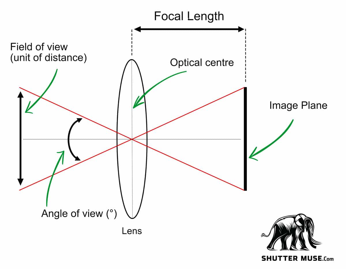
You’ll often see one of two terms referring to a distance sensor’s capabilities: Angle of View or Field of View. While the term “Angle of View” is more accurate, you’ll most often see “Field of View” in documentation for these sensors. Angle of View describes the shape of the cone projected from the sensor within which a signal is either emitted or received and its value is measured in degrees. True Field of View describes the plane perpendicular to the sensor at any given distance that is bounded by the Angle of View. Note that a sensor’s emitter and receiver may have different Angles of View but they are designed to overlap to the greatest extent possible. Figure 1 illustrates the relationship between angle of view and field of view.
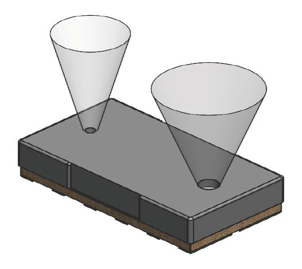
Figure 2 shows a typical distance sensor’s two main elements, the emitter and the receiver, showing the the angle of transmission from the transmitter and angle of view from the receiver. They sit beside each other on the device, pointing the same direction.
Features of a Distance Sensor
Whether you’re dealing with an IR proximity sensor, LiDAR distance sensor, or time of flight sensor, there are a few features you’ll need to consider:
- Range – Distance sensors come with different minimum and maximum ranges.
- Resolution – How granular the units of measurement. Not to be confused with a sensor’s accuracy.
- Field of View – More accurately described as Angle of View when measured in degrees, the Field of View describes the area in which a target will trigger a reading at a given distance from the sensor.
- Susceptivity to ambient light conditions – With the exception of ultrasonic sensors, the presence of ambient light will affect a distance sensor’s performance. Direct light is more disruptive than indirect, outdoor light more so than indoor, and incandescent light sources more so than artificial.
- Some target properties will affect the sensor’s response. For example, large faceted shapes or concave shapes (like the inside of a bowl, or a hat) might not reflect the beam back to the sensor well. Other factors which could affect the response include:
- size
- orientation (wrt the sensor)
- color
- transparency
- reflectance
- texture
- Electrical Characteristics – As with any electronic sensor, you should pay attention to current consumption and make sure the rated voltage of your distance sensor is compatible with your microprocessor.
- Interface – Distance sensors come with a variety of interfaces. Some provide a changing analog voltage based on range. Others will provide a UART asynchronous or an I2C synchronous serial interface. Ultrasonic distance sensors will provide a changing pulse width that corresponds with the changing properties of the sensor. Nowadays, most light-based distance sensors are I2C.
- Extra Features – in addition to the basic physical properties, some distance sensors will have additional features, like the ability to measure ambient light, rudimentary gesture detection, or sophisticated control features like the ability to set angle of view or specific regions of interest (ROI).
For more on choosing a distance sensor, Digi-Key has a decent introductory guide and SparkFun has a well organized comparison guide.
Most vendors of sensor modules do not actually make the sensors themselves, they just put them on a breakout board along with the reference circuit, for convenience. While you might buy your distance sensor from Sparkfun, Adafruit, Seeed Studio, or Pololu, for example, the chances are the actual sensor is manufactured by another company like AMS, Sharp, ST Microelectronics, or Vishay. When you shop for a sensor module, check out the manufacturer’s datasheet in addition to the vendor’s tech specs. It’s also worth doing a comparison search with the sensor part number on Octopart.com to see who else might make a breakout board.
Ultrasonic Distance Sensors
Ultrasonic distance sensors use a transducer to emit a pulse of ultrasound at 40 MHz measuring the time it takes for the pulse to bounce off the target and return to the sensor and calculating distance based on the speed of sound. Although it’s unusual to see them described as such, technically they are a sonic time-of-flight sensor. Ultrasonic distance sensors are immune to ambient lighting conditions and target transparency however because sound transmission is influenced by the physical properties of air, accuracy is affected by ambient sound, temperature, and humidity. A ‘soft’ sound absorbing target with a surface covered by cloth will impact accuracy, as will a target with an irregular surface.
HC-SR04 distance sensors are a staple of many starter kits built around the Arduino Uno, which means they are not plug-and-play compatible with 3.3V Arduino boards like the Nano 33 IoT. It’s simple enough to incorporate a voltage divider into your circuit, however, and if you’re feeling adventurous, the HC-SR04 can be permanently modified for use with either 3.3V or 5V logic.
SparkFun’s Ultrasonic Distance Sensor (also their Zio Ultrasonic Distance Sensor Qwiic version), and Adafruit’s Ultrasonic Sonar Distance Sensor are variants of the HC-SR04. They are inexpensive and ubiquitous. Alternatively, Adafruit’s RCWL-1601 Ultrasonic Distance Sensor and Seeed’s Grove – Ultrasonic Distance Sensor are more flexible, designed to work with either 3.3V or 5V logic out of the box, and comparably priced
Infrared LED Proximity Sensors
The simplest approach to measuring distance using infrared light is to measure the amount of emitted IR light that bounces off a target and reflects back to the sensor. The ranges are relatively small — between 0 and 20cm — and the language used is ‘proximity’ rather than ‘distance’.
Measuring proximity is often one capability of sensors that also measure other aspects of light, such as the Adafruit VCNL4040 Proximity and Lux Sensor and the SparkFun Proximity Sensor Breakout – 20cm, VCNL4040 (Qwiic) which measure ambient light levels. Color and gesture sensors based on the Avago APDS-9960 also provide proximity readings, including the Adafruit APDS9960 Proximity, Light, RGB, and Gesture Sensor and the SparkFun RGB and Gesture Sensor – APDS-9960. A lab exercise on the APDS-9960 can be found on this site.
Infrared LED Time-of-Flight Sensors
Some optical time-of-flight distance sensors are based on IR LED emitters. They can be pricey. The Benewake TFmini sold by Adafruit, SparkFun and Seeed is capable of ranging distances up to 12 meters and while it requires 5V to operate, it uses 3.3V logic to communicate. Unlike other distance sensors that use I2C, the TFmini uses the UART protocol for asynchronous serial communication.
The Garmin LIDAR-Lite V4 — available at Adafruit and SparkFun (also available with Qwiic connector) — has a 10 meter range and is more expensive than the Benewake sensor but comes with some additional features including I2C serial protocol and wireless control using Garmin’s open ANT Protocol, a low power wireless protocol alternative to BLE.
Note that both Benewake and Garmin take creative license and, while not technically accurate, nonetheless market the two products above as ‘LiDAR’ distance sensors.
Infrared LED Triangulation Sensors
Another method for calculating distance using infrared light is triangulation. A pulse of IR light is emitted and range is determined based on the angle of reflection. Most of the maker / hobbyist sensors of this category are manufactured by Sharp. They come in both analog and digital output variations but because most of them require 5V, they can be used with the Uno but not the Nano 33 IoT. The Sharp GP2Y0A60SZLF is an exception, operating at 3V. Pololu makes a breadboard-friendly module with this sensor.
Maximum distances for analog output sensors range from 5cm to 80cm depending on the model. For sensors with digital output, maximum distances range from 1.5cm to 550cm.
LiDAR Distance Sensors
LiDAR distance ranging sensors like the Garmin LIDAR-Lite v3 available from Adafruit and SparkFun use time-of-flight to calculate distance as a function of the time it takes a pulse of emitted laser light to reflect off a target and return to the sensor. The Garmin LIDAR-Lite v3 is capable of very rapid readings measuring distances up to 40 meters although at a resolution of centimeters rather than millimeters. Data can be sent to the microprocessor as either a digital signal using I2C or an analog signal using pulse width modulation. Distance sensors of this kind are often used in robotics and autonomous vehicles; they are quite expensive and less likely to be of practical use to PComp projects.
LiDAR is an acronym for light detection and ranging pr laser imaging, detection, and ranging. Note that some distance sensors marketed as LiDAR are actually lensed IR LED time-of-flight sensors and do not actually user lasers.
VCSEL (Vertical Cavity Surface Emitting Laser) Sensors
Another example of optical time-of-flight, these distance sensors combine a vertical cavity surface emitting laser (VCSEL) with a single-photon avalanche diode (SPAD) array to measure the time it takes a photon of light to travel from the sensor, to the target, and back. Distance is then calculated using the speed of light, which is a constant. VCSEL distance sensors provide true laser-based ranging with high resolution (millimeters rather than centimeters) in a very small form factor. ST’s VL53L0X and ST’s VL53L1X are VCSEL sensors. A lab exercise on the VL53L0x sensor can be found on this site.
RADAR
RADAR is an acronym for Radio Detection and Ranging. Radar is a technology that dates back to the 1940’s. Despite being a mature technology, though, it is still not as inexpensive or as ubiquitous as other forms of distance ranging. Seeed Studio makes a Doppler Radar module, however, for those interested in radar: Seeed Grove Doppler Radar
What To Look For in a Distance Sensor Library
Different vendors will often write their own libraries for the distance sensors they sell. When you’re looking at a given vendor’s product, take a look at the properties of the sensor in the vendor’s datasheet, and the list of public functions in the library’s API. Does the library give you the functions of the sensor that you need? If the sensor supports multiple sensing ranges, does the library give you access to setting and getting the range? Is it well-documented, and well-commented? Are there simple, clear, well-commented examples?
For example, both SparkFun and Pololu make breakout boards for the VL53L1X Time-of-Flight sensor. The VL53L1X is typical of a next gen distance sensor; it’s got an I2C interface, operates at 2.8V, and offers a large range from 4cm to 400cm. The SparkFun hookup guide is more accessible than the Using the VL53L1X section on Pololu’s product page but neither provides a summary of all the functions in their libraries. To see that, you need to look at the header files for each library.
Pololu offers two different libraries for the VL53L1X. The Pololu VL53L1X library is streamlined to use less resources but doesn’t surface some of the more technical features of the sensor. On the other hand, the Pololu ST VL53L1X API library is a largely literal implementation of ST’s VL53L1X Full API, providing more advanced functionality at the expense of a larger memory footprint and a more opaque code base divided into multiple header files geared less toward the student or hobbyist than someone with an electrical engineering background.
By comparison, SparkFun’s header file is less verbose and significantly shorter than either of the Pololu offerings with clean, succinct, in-line comments that make it accessible and easy to navigate. The public functions start around line 35. Both are functional libraries, though, and you should choose based on the features you want and how easy you find each to use.
You can find further notes on how to pick a library in this lab exercise for the APDS-9960 Color, Light, and Gesture sensor.
Conclusion
There are dozens of distance sensors on the market, and as they become more ubiquitous in electronic devices, they continue to get smaller, cheaper, more sophisticated and more power-efficient. The principles laid out here should give you a basis for assessing new sensors as needed.
Additional Links
- Intangible Interactions course – including a guide to choosing a distance sensor
- Digi-Key » Fundamentals of Distance Measurement and Gesture Recognition Using ToF Sensors
- Seeed Studio Blog » Types of Distance Sensor and how to select one?
- SparkFun » Distance Sensing Overview
- SparkFun » Distance Sensor COmparison Guide
- Terabee » Choosing the Right Distance Sensor for Your Application