Introduction
The HC-SR04 distance sensor is an inexpensive and ubiquitous distance sensor that gives reasonably reliable distance readings in the 2cm – 4m range. In this lab, you’ll learn how to use this sensor with an Arduino microcontroller. There are dozens of similar tutorials for this sensor all over the web.
What You’ll Need to Know
To get the most out of this Lab, you should be familiar with the following concepts beforehand. If you’re not, review the links below:
- What is a microcontroller
- Beginning programming terms
- What variables are
- The basics of electricity
- What is a solderless breadboard
- The basics of Digital input and output with Arduino
- The basics of distance sensors
Things You’ll Need
Figures 1-4 show the parts you’ll need for this exercise. Click on any image for a larger view.


How the Sensor operates
The HC-SR04 sensor operates by sending out a 40KHz ultrasonic signal and waiting for it to bounce off the subject and return to the sensor. Since the speed of sound in air is reasonably constant, you can estimate the distance to the subject by reading the time taken for the sound to return.
To operate the sensor, you send a 10-microsecond low-to-high pulse on the sensor’s trigger pin. This causes the sensor to send out the ultrasonic signal. Then you measure length of the pulse on the echo pin to know how long the signal took to return.
The Circuit
This sensor operates on 5V. With the Uno, that’s the default supply voltage of the board. If you are using a 3.3V board like the Nano 33 IoT, you’ll need to make sure you’re powering it with 5V. You can get that from the USB input, or from the external voltage input if you are using a 5V source. You’ll need to attach the sensor’s voltage input to the VUSB pin, which should output 5V when attached to USB, or to the Vin pin if you are powering the Nano 33 IoT with 5V.
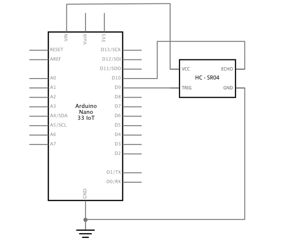
Figures 5 and 6 show the schematic diagram and breadboard layout of the sensor attached to an Arduino Nano 33 IoT.

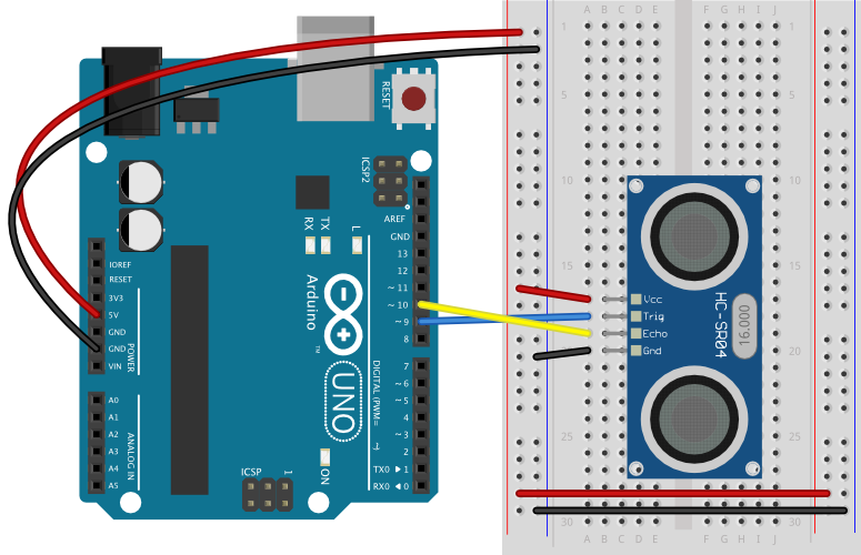
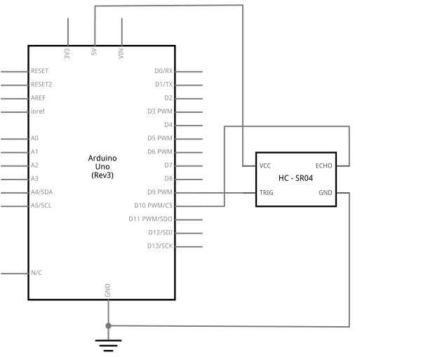
Figures 7 and 8 show the schematic diagram and breadboard layout of the sensor attached to an Arduino Uno. Since the Uno operates on 5V, you can use the +5V output pin from the Uno to power the sensor.
The Code
The sketch to read the sensor follows the instructions described above. First you take the trigger pin low. Then you take it high to initiate the trigger pulse, then wait ten microseconds. Then you take it low again, ending the trigger pulse. Then you use the pulseIn() command to measure the length of the pulse on the echo pin. After that, you do the math to convert the pulse time to centimeters, and you’re done.
// set up pin numbers for echo pin and trigger pins:
const int trigPin = 9;
const int echoPin = 10;

void setup() {
  // set the modes for the trigger pin and echo pin:
  pinMode(trigPin, OUTPUT);
  pinMode(echoPin, INPUT);
  // initialize serial communication:
  Serial.begin(9600);

}

void loop() {
  // take the trigger pin low to start a pulse:
  digitalWrite(trigPin, LOW);
  // delay 2 microseconds:
  delayMicroseconds(2);
  // take the trigger pin high:
  digitalWrite(trigPin, HIGH);
  // delay 10 microseconds:
  delayMicroseconds(10);
  // take the trigger pin low again to complete the pulse:
  digitalWrite(trigPin, LOW);

  // listen for a pulse on the echo pin:
  long duration = pulseIn(echoPin, HIGH);
  // calculate the distance in cm.
  //Sound travels approx.0.0343 microseconds per cm.,
  // and it's going to the target and back (hence the /2):
  int distance = (duration * 0.0343) / 2;
  Serial.print("Distance: ");
  Serial.println(distance);
  // a short delay between readings:
  delay(10);
}
Clear the Sensing Zone
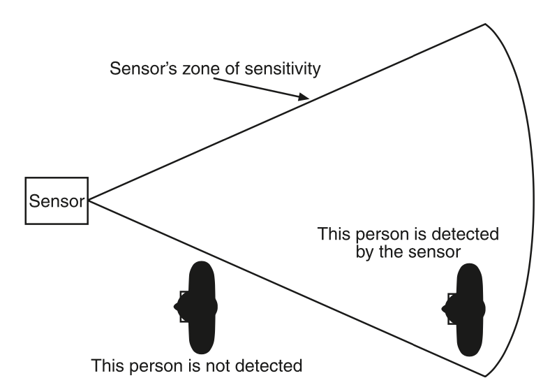
All distance sensors send out their signal and listen for a response in a particular sensing field of view. Figure 9 shows a distance sensor’s typical field of view. The field moves out from the sensor in a cone. It is smaller nearest the sensor, and gets wider as distance from the sensor gets larger. The nearest object in the field of view is the one detected. A person standing outside the field of view cannot be detected by the sensor.
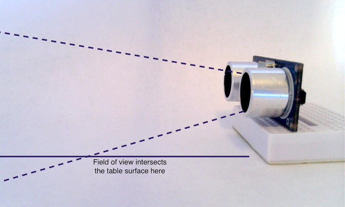
Similarly, an object in the field of view can be detected whether you intend it to or not. Figure 10 shows an ultrasonic sensor sitting on a table. The field of view of the sensor extends out from the sensor, and intersects the table a few centimeters from the sensor. This stops the sensor from picking up more distant targets.
For more on distance sensors, see Distance Sensors: the Basics.