Introduction
Rotary encoders are sensors which sense the rotation of a central shaft. Unlike a rotary potentiometer, encoders can turn infinitely, covering the full 360 degrees of the shaft’s rotation. Many have built-in pushbuttons as well. Encoders are often used to measure the rotation of a vehicle’s wheel or axle as well. In this lab, you’ll learn how to use a rotary encoder as an input to a microcontroller.
What You’ll Need to Know
To get the most out of this Lab, you should be familiar with the following concepts beforehand. If you’re not, review the links below:
- What is a microcontroller
- Beginning programming terms
- What variables are
- The basics of electricity
- What is a solderless breadboard
- The basics of Digital input and output with Arduino
Things You’ll Need
Figures 1-4 show the parts you’ll need for this exercise. Click on any image for a larger view.


How the Sensor operates
Rotary encoders measure rotation using two internal switches very close together, and a rotating disk. The disk has holes in it, and when the it passes each switch, the switch opens then closes. The switches open and close out of phase with each other, and the resulting pattern of open and close lets you detect the rotation. This is called quadrature encoding. Figure 5 shows a quadrature wheel and the positions of two switches relative to the wheel.
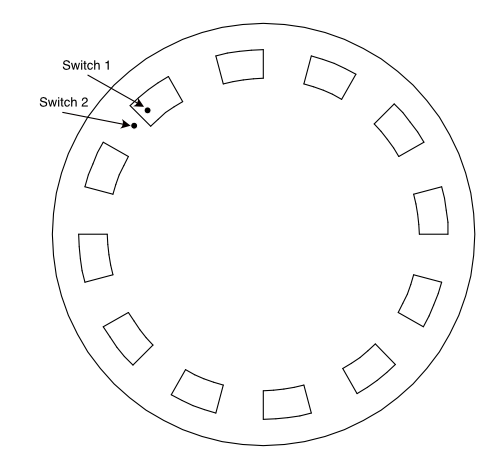
Paul Stoffregen’s encoder library page has a nice animation illustrating this pattern under the heading Understanding Quadrature Encoded Signals.
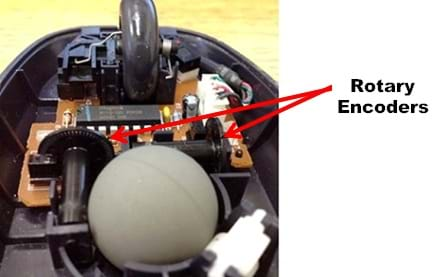
The sensors in an encoder may be mechanical or optical. Optical sensors (photodiodes) are often used to reduce mechanical wear on the sensor. Optical encoder wheels were common in early computer mice. You can see one in Figure 6, which comes from teachengineering.com
An encoder doesn’t tell you its absolute position, but it does tell you whether it’s rotating left or right, depending on the pattern of the sensor changes. The amount of rotation, and therefore the resolution of the encoder, depends on how many holes the encoder has. The more holes, the more finely you can read the change in rotation.
Encoders are often used as knobs that can turn a full 360 degrees, but they are also used in other applications to sense a changing rotation. Wheel encoders and shaft encoders can be used to count revolutions of a vehicle’s axle, for example. In this lab you’ll see how to use a knob-style encoder.
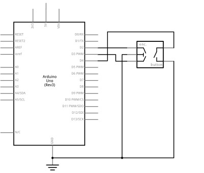
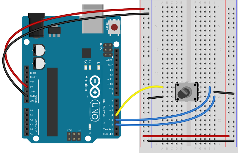
The Circuit
To use an encoder, you connect its two switches to two digital input pins of your microcontroller and look for changes. Because they can happen very fast, it’s wise to use inputs which can be hardware interrupts, meaning that they can read change as soon as the pin changes, not just when you use the digitalRead() command.
Figures 7 through 10 show how to connect an encoder with a pushbutton to an Arduino Nano 33 IoT or an Arduino Uno. For the Nano 33 IoT, any pin can act as a hardware interrupt pin. This lab uses pins 2 and 3 for compatibility with the Uno’s interrupts.
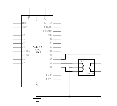
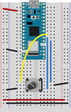
The wiring for an Arduino Uno is similar to the Nano 33 IoT, but the Nano has only two hardware interrupts, pins 2 and 3. It’s best to use those. If you are using a Nano 33 IoT, you can use any of that board’s interrupt pins if you wish instead. Those are pins 2, 3, 9, 10, 11, 13, A1, A5, and A7.
The Code
There are several libraries for reading interrupts. One of the earliest is Paul Stoffregen’s Encoder library referenced above, on which many others are based. That library doesn’t work with the Nano’s interrupts, however, so the examples below use Manuel Reimer’s EncoderStepCounter library instead.
To install it, search the Arduino IDE’s library manager for EncoderStepCounter by Manuel Reimer.
To read an encoder with the Encoder library, you include the library at the top, make an instance of the library in a variable in which you define the pins for the encoder. Then when you want to read the encoder, you call the .read() command. Here’s a basic example:
#include <EncoderStepCounter.h>

// encoder pins:
const int pin1 = 9;
const int pin2 = 10;
// Create encoder instance:
EncoderStepCounter encoder(pin1, pin2);

// encoder previous position:
int oldPosition = 0;

void setup() {
  Serial.begin(9600);
  // Initialize encoder
  encoder.begin();
}

void loop() {
  // if you're not using interrupts, you need this in the loop:
  encoder.tick();
  // read encoder position:
  int position = encoder.getPosition();

  // if there's been a change, print it:
  if (position != oldPosition) {
    Serial.println(position);
    oldPosition = position;
  }
}
When you run this, you’ll see that the position value goes up in one direction and down in the other. There is no absolute position; unlike a potentiometer, which measures an absolute resistance at a particular position of the wiper, an encoder reads only change in one direction or another. It doesn’t know where it is in the rotation, only how many steps it’s taken since it started counting steps.
Most knob-style encoders change with every click of the shaft. This is typical with many encoders. These clicks are called detents, and they are built into the shaft to give you a sense of its movement.
The EncoderStepCounter library will work on any digital pins of your board, but if you are not using interrupts, it may skip a step or two if you are turning the encoder fast. For this reason, it won’t work well for encoders that are not turned by a human hand, like the shaft encoders on many motors. You can correct for that by attaching it to interrupt pins, as described above. If you use interrupt pins, change your setup function as follows:
void setup() {
  Serial.begin(9600);
  // Initialize encoder
  encoder.begin();
  // Initialize interrupts
  attachInterrupt(digitalPinToInterrupt(pin1), interrupt, CHANGE);
  attachInterrupt(digitalPinToInterrupt(pin2), interrupt, CHANGE);
}
Then add a new function to handle the interrupts that will be generated:
// Call tick on every change interrupt
void interrupt() {
  encoder.tick();
}
If you enable interrupts like this, you won’t need the call to encoder.tick() in the loop() function.
When you run the sketch this time, you should see that the step value is changing once for each detent of the encoder shaft, and doesn’t miss steps.
If you want to make the step count reset itself when it reaches a maximum number of steps, you can do that by by changing the loop as shown below. This line resets the step counter every 24 steps by using the modulo, or remainder, operator (%):
void loop() {
  // if you're not using interrupts, you need this in the loop:
  encoder.tick();

  // read encoder position:
  int position = encoder.getPosition();

  if (position % 24 == 0) {
    encoder.reset();
    position = encoder.getPosition();
  }
  // if there's been a change, print it:
  if (position != oldPosition) {
    Serial.println(position);
    oldPosition = position;
  }
}
Rollover like this can be useful if you want the value to reset once per rotation.
The Pushbutton and Internal Pullup Resistors
Most knob-style encoders have a pushbutton built in as well, and you wired the encoder’s pushbutton in the diagram above. You may have noticed that it’s wired differently than you did in the digital in and out lab. There’s no pulldown resistor, and the pushbutton is wired to ground. What’s going on?
Many microcontrollers (including all Arduino models) have internal pullup resistors on the input pins. These function in the opposite way of a pulldown resistor: they pull the pin up to voltage when there’s no other connection. When you use an internal pullup resistor, you wire your pushbutton to ground instead of to voltage, and the pin goes low when you press the button. This saves you one resistor; all you have to do is to wire your pushbutton to ground from the digital input pin, and declare the pin’s mode like so: digitalWrite(buttonPin, INPUT_PULLUP); You’ll see it in the example below:
void setup() {
  // set the encoder's pushbutton to use internal pullup resistor:
  pinMode(4, INPUT_PULLUP);
  Serial.begin(9600);
}

void loop() {
  int buttonState = digitalRead(4);
  Serial.println(buttonState);
}
Upload this code to your board with the circuit as shown in figures 7 through 10, then open the serial monitor. Press the encoder push the encoder’s pushbutton to see how the state changes.
Putting It all Together
Using an encoder and its pushbutton together gives you a great way to let a user choose from a range of choices. By reading the changing encoder state, you can get the range, and by reading the pushbutton, you can get the one they chose. Here’s an example that reads both the encoder and the pushbutton to do just that:
#include <EncoderStepCounter.h>

const int pin1 = 2;
const int pin2 = 3;

// Create encoder instance:
EncoderStepCounter encoder(pin1, pin2);

// encoder previous position:
int oldPosition = 0;

const int buttonPin = 4;    // pushbutton pin
int lastButtonState = LOW;  // last button state
int debounceDelay = 5;      // debounce time for the button in ms


void setup() {
  Serial.begin(9600);
  // Initialize encoder
  encoder.begin();
  // Initialize interrupts
  attachInterrupt(digitalPinToInterrupt(pin1), interrupt, CHANGE);
  attachInterrupt(digitalPinToInterrupt(pin2), interrupt, CHANGE);
  // set the button pin as an input_pullup:
  pinMode(buttonPin, INPUT_PULLUP);
}

void loop() {
  // if you're not using interrupts, you need this in the loop:
  encoder.tick();

  // read encoder position:
  int position = encoder.getPosition();
  // read the pushbutton:
  int buttonState = digitalRead(buttonPin);
  //  // if the button has changed:
  if (buttonState != lastButtonState) {
    // debounce the button:
    delay(debounceDelay);
    // if button is pressed:
    if (buttonState == LOW) {
      Serial.print("you pressed on position: ");
      Serial.println(position);
    }
  }
  // save current button state for next time through the loop:
  lastButtonState = buttonState;

  // reset the encoder after 24 steps:
  if (position % 24 == 0) {
    encoder.reset();
    position = encoder.getPosition();
  }
  // if there's been a change, print it:
  if (position != oldPosition) {
    Serial.println(position);
    oldPosition = position;
  }
}

// Call tick on every change interrupt
void interrupt() {
  encoder.tick();
}
Upload this code to your Arduino. When you turn the knob, you’ll run through 24 possible values (0 to 23), and when you press the pushbutton, you’ll be told what the knob value was when you pressed. Used like this, encoders can be another way to get a range of values, when a potentiometer doesn’t feel right for your application.
The full code for this example can be found at this link.
What Can I Do With An Encoder?
You could set the hands of a clock, for example. Or you can change the brightness of a light, or the volume of a sound. One of the advantages to an encoder, as opposed to a potentiometer, is that it can rotate endlessly. This means that the quantity that you’re changing doesn’t have to be related to the position of the encoder knob, only to its change.
More Info
For more on encoders, see:
- If you want an encoder library that also reads the encoder’s pushbutton, try EncoderTool.
- A few other encoder examples using Paul Stoffregen’s library by Tom Igoe
- For more on the lower level details of encoders, see this tutorial by Adam Meyer.
- Stoffregen’s library also includes an explanation of the details, at this link. An example written with this algorithm, using no libraries can be found at this link.