Introduction
Transistors are often used as electronic switches, to control loads which require high voltage and current from a lower voltage and current. The most common example you’ll see of this in a physical computing class is to use an output pin of a microcontroller to turn on a motor or other high current device. The output pins of a microcontroller can only produce a small amount of current and voltage. But when coupled with a transistor, they can control much more.
What You’ll Need To Know
You should have read the notes on high current loads before doing this lab. In order to get the most out of this lab, you should know the basics of electronics, as well as how to use a solderless breadboard. It would help to do some reading on DC motors as well.
Microcontrollers aren’t the only integrated circuits that produce a low voltage and current on their output pins. There are many components that do this. You’ll see a whole range of so-called logic ICs that can’t produce very much current or voltage, but can produce a small change on their output pins that can be read as a data or control signal. The output voltage from devices is often referred to as a logic or a control voltage, as opposed to the supply or load voltage needed to control the high-current device. You can use transistors from circuits like these. For example, you might put a transistor on the output pin of a 555 timer IC (which produces a variable timing pulse), or a shift register IC (which allows you to produce multiple control signals in parallel) to control high current loads from those devices.
Things You’ll Need
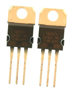
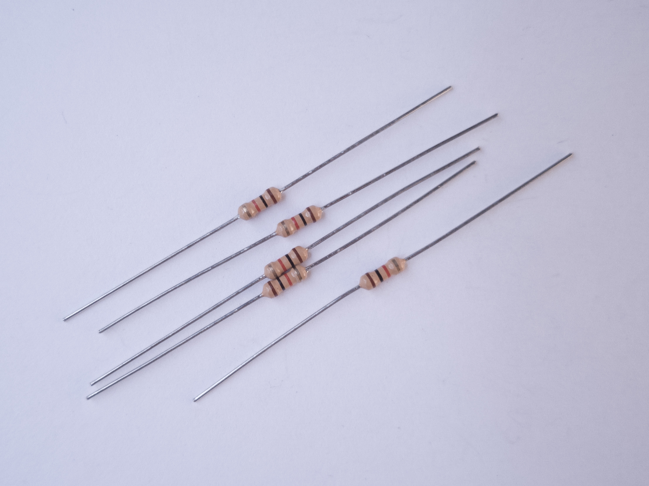
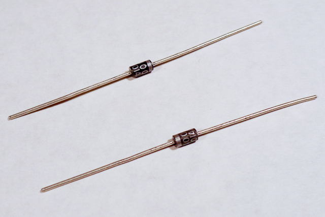
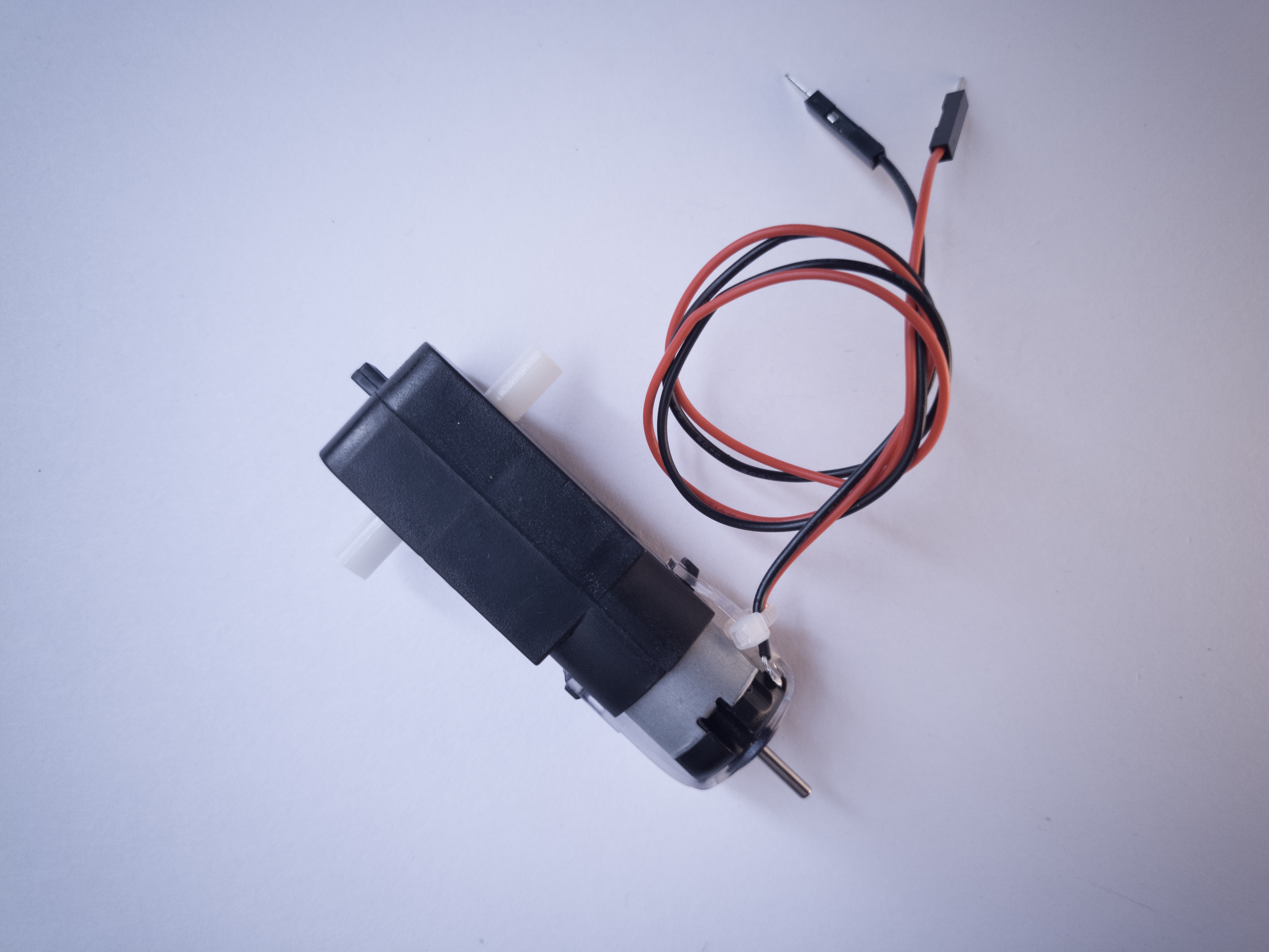
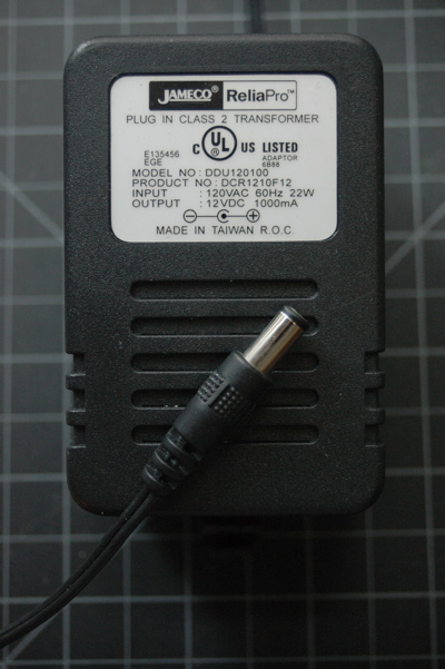
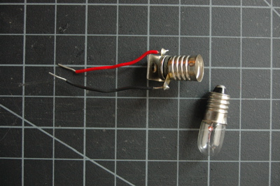
Figures 1-12 are the parts you’ll need for this exercise.


Set Up the Breadboard
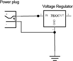
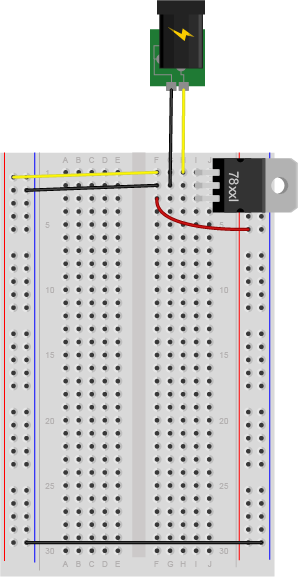
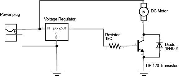
Connect a 7805 5V voltage regulator to your board, and power it from a 9-12V DC power supply. Connect the ground rows on the sides together. Don’t connect the two red rows on the side of the breadboard to each other, though. Wire the breadboard so that the right side of the board receives the 5V output from the regulator, but the left side gets 9-12V directly from your DC power supply. The 5V line is the 5-volt bus or logic supply and the 9-12V line is the high-voltage bus or load supply. The two ground lines are ground. Figure 13 shows the schematic drawing and Figure 14 shows the breadboard view of the circuit explained here.
Add a Motor and Transistor
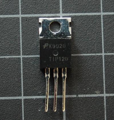
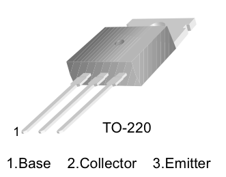
The transistor allows you to control a circuit that’s carrying higher current and voltage from the a lower voltage and current. It acts as an electronic switch. The one you’re using for this lab is an NPN-type transistor called a TIP120. The datasheet for it can be found here. It’s designed for switching high-current loads. It has three connections, the base, the collector, and the emitter as shown in Figure 15 and Figure 16. Attach high-current load (i.e. the motor or light) to its power source, and then to the collector of the transistor. Then connect the emitter of the transistor to ground. Then to control the motor, you apply voltage to the transistor’s base. When there’s at least a 0.7V difference between the base and the emitter, the transistor will “turn on” — in other words, it’ll allow voltage and current to flow from the collector to the emitter. When there’s no voltage difference between the base and the emitter, the transistor turns off, or stops the flow of electricity from collector to emitter.

Using a MOSFET instead of a TIP120

You can also use an N-channel MOSFET transistor for this. The diagram and schematic symbols are shown above in Figure 17. The IRF520 and the FQP30N06L MOSFETs are similar in function, and have the same pin configuration as the TIP120, and perform similarly. They can handle more amperage and voltage, but are more sensitive to static electricity damage.
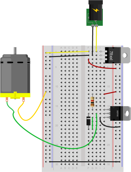
Connect a 1-kilohm resistor from the transistor’s base to another row of the breadboard. This resistor will limit the current to the base.
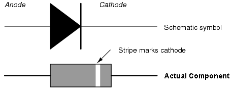
You also need to add a diode in parallel with the collector and emitter of the transistor, pointing away from ground as shown in Figure 18 and Figure 19. The diode to protects the transistor from back voltage generated when the motor shuts off, or if the motor is turned in the reverse direction. This is called a snubber diode, or protection diode. Related topics: Transistors, Relays, and Controlling High-Current Loads
Be sure to add the diode to your circuit correctly. The silver band on the diode denotes the cathode which is the tip of the arrow in the schematic, as shown in Figure 20:
This circuit assumes you’re using a 12V motor. If your motor requires a different voltage, make sure to use a power supply that’s appropriate. The TIP120 transistor can handle up to 30V across the collector and emitter, so make sure you’re not exceeding that. Connect the ground of the motor’s supply to the ground of your microcontroller circuit, though, or the circuit won’t work properly.
Add a Switch to Control the Transistor
To turn on the transistor, you need a voltage difference between the base and the emitter of at least 0.7V. Since the emitter is attached to ground, that means any voltage over 0.7V applied to the base will turn the transistor on.
- Connect a wire from the 5-volt bus of the board (also called the regulated voltage bus) to the other end of the 1 kilohm resistor as shown above and you should see the motor turn on.
Of course, it’s inconvenient to connect and disconnect a wire like this, so use a switch instead.
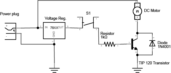
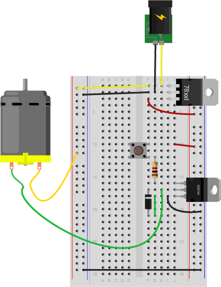
- Remove the red wire connecting the resistor to 5 volts and connect one side of a pushbutton or switch to the 5-volt bus, and the other side to the 1K resistor. Figure 21 shows the schematic drawing and Figure 22 shows the breadboard view of the circuit.
Change the Switch for a Potentiometer
The voltage on the base of the transistor doesn’t have to be controlled by a switch. You can use a potentiometer, connected as a voltage divider, to produce a changing control voltage for the transistor’s base. Figure 23 shows the schematic drawing and Figure 24 shows the breadboard view of the circuit. Related video: Connecting the potentiometer
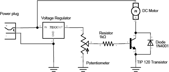
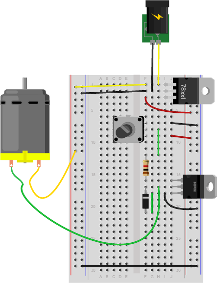
When you turn the potentiometer, you’re producing a varying voltage on the wiper pin. That means you’re changing the voltage on the base of the transistor. Yet the motor doesn’t change its speed. It only turns on or off. When the voltage on the potentiometer’s wiper pin reaches 0.6V, the transistor will turn on. When it’s below 0.6V, the transistor will turn off. The transistor is acting like a switch, not a variable supply. If you want to vary the motor’s speed using a transistor, you need to turn the transistor on and off very fast, and change the ratio of on time to off time. This is called pulse width modulation. You’ll learn more about it in these notes on analog output from a microcontroller and see it in action in the analog lab.
Change the Potentiometer for a Voltage Divider
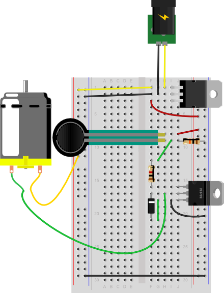
If you’ve understood everything so far and managed to get it to work, here’s where it gets really fun. Imaging you have a variable resistor and you want the motor to turn on when the variable resistor passes a particular threshold. For example, maybe you want to turn on the motor when a temperature changes on a thermistor (temperature sensitive resistor), or when a weight is placed on a force-sensing resistor. To make this happen, change your control circuit to include a variable resistor as shown in Figure 25 and Figure 26.
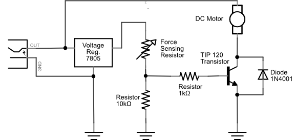
Using a Voltage Divider to Control a Transistor
Extra credit: See if you can work out the correct resistor value for the fixed resistor of the voltage divider that will produce just the right voltage to turn the motor on when you turn on your room’s lights, and off when you turn them off.
Whoa, that blew my mind. How do I do that?
You know you need 0.7V to turn the transistor on, and less than that to turn it off. You know how to measure the resistance of a variable resistor. So find the resistance of your variable resistor with the lights on and with the lights off, and calculate what fixed resistor will give you 0.6V. The input to your voltage divider here is 5V. That means you want 4.3 volts across the variable resistor. You know that the output voltage is proportional to the ratio of the two resistors. And you know that the current running between them is the same, because they are in series. So:Voltage = current * resistance 4.3V = current * photocell resistance
therefore,current = 4.3V / variable resistor resistance
Then apply this to the fixed resistor:0.7V = current * fixed resistor resistance
therefore,fixed resistor resistance = current / 0.7V
or:fixed resistor resistance = (4.3V / variable resistor resistance) / 0.7V
If you’re using a force sensing resistor as your variable resistor (an Interlink model 402 is shown here), you’ll probably find that they’re very sensitive. They tend to be greater than 10 megohms resistance when no force is on them and near zero when pressed. See the graph on page 3 of the datasheet for the voltage output for various fixed resistor values.
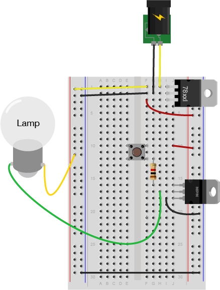
Connect a lamp instead
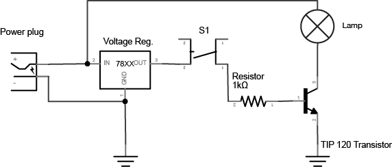
You could also control a lamp using a transistor. Figure 27 shows the schematic drawing and Figure 28 shows the breadboard view of the circuit. Like the motor, the lamp circuit below assumes a 12V lamp. Change your power supply accordingly if you’re using a different lamp. In the lamp circuit, the protection diode is not needed, since there’s no way for the polarity to get reversed in this circuit:
Conclusion
A motor controlled like this can only be turned in one direction. To be able to reverse the direction of the motor, an H-bridge circuit is required. For more on controlling DC motors with H-bridges, see the DC Motor Control lab.