Skip to content

ITP Physical Computing

  • Syllabus Pages
    • Syllabus Fall 2025
    • Assignments
    • Week-to-Week Activity
    • Journals & Documentation
  • Lessons
  • Videos
  • Labs
  • Resources
    • Parts And Tools Guide
    • Microcontroller Pin Functions
    • Breadboard Layouts
    • Introduction to the Nano 33 IoT
    • Introduction to the Nano R4
    • Construction Links
    • Related Books and Articles
    • External Links and Resources
    • Tips from Instructors
  • Pcomp @ ITP
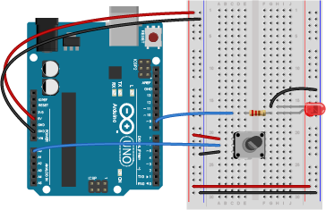
Previous Image
Next Image

potentiometer_led_bb

Breadboard drawing of a potentiometer connected to analog in 0 of an Arduino and an LED connected to digital pin 9. An Arduino Uno on the left connected to a solderless breadboard, right. The Uno's 5V output hole is connected to the red column of holes on the far left side of the breadboard. The Uno's ground hole is connected to the blue column on the left of the board. The red and blue columns on the left of the breadboard are connected to the red and blue columns on the right side of the breadboard with red and black wires, respectively. These columns on the side of a breadboard are commonly called the buses. The red line is the voltage bus, and the black or blue line is the ground bus. On the breadboard, a potentiometer is connected to pins 21 through 23 in the left center section of the board. A red wire connects row 21 in the left center section to the voltage bus on the left side. A black wire connects row 23 in the left center section to the ground bus on the left side. A blue wire connects row 22 to the Arduino's analog in pin 0. A 220-ohm resistor straddles the center divide of the breadboard, connecting to row 17 on both sides. In the left center section of the breadboard, a blue wire connects row 17 to pin D9 of the Arduino. In the right center section, the anode of an LED is connected to row 17. The cathode of the LED is in row 16. A black wire connects row 16 to the ground bus on the right side of the board.

Breadboard view of a potentiometer connected to analog in 0 of an Arduino and an LED connected to digital pin 9.

Posted on August 28, 2014August 14, 2018 Full size 364 × 235

Post navigation

Published inLab: Analog In with an Arduino
QR code of this site's URL

Find Content by Category:

  • Syllabus Pages
    • Syllabus Fall 2025
    • Assignments
    • Week-to-Week Activity
    • Journals & Documentation
  • Lessons
  • Videos
  • Labs
  • Resources
    • Parts And Tools Guide
    • Microcontroller Pin Functions
    • Breadboard Layouts
    • Introduction to the Nano 33 IoT
    • Introduction to the Nano R4
    • Construction Links
    • Related Books and Articles
    • External Links and Resources
    • Tips from Instructors
  • Pcomp @ ITP
ITP Physical Computing Proudly powered by WordPress