Introduction
This is an introduction to basic analog input on a microcontroller. In order to get the most out of it, you should know something about the following concepts. You can check how to do so in the links below:
- Electrical circuits
- What a microcontroller is and what it can do
- Digital input and output on a microcontroller
These video links will help in understanding analog input:
Analog Input
While a digital input to a microcontroller can tell you about discrete changes in the physical world, such as whether the cat is on the mat, or the cat is off the mat, there are times when this is not enough. Sometimes you want to know how fat the cat on the mat is. In order to know this, you’d need to be able to measure the force the cat exerts on the mat as a variable quantity. When you want to measure variably changing conditions like this, you need analog inputs. An analog input to a microcontroller is an input that can read a variable voltage, typically from 0 volts to the maximum voltage that powers the microcontroller itself.
Many transducers are available to convert various changing conditions to changing electrical quantities. There are photocells that convert the amount of light falling on them to a varying resistance; flex sensors that change resistance as they are bent; Force-sensitive resistors (FSRs) that change resistance based on a changing force applied to the surface of the sensor; thermistors that change resistance in response to changing heat; and many more.
Related video: Resistors, variable resistors, and photocells
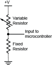
In order to read these changing resistances, you put them in a circuit and pass a current through them, so that you can see the changing voltage that results. There are a few variations on this circuit. The simplest is called a voltage divider. Because the two resistors are in series voltage at the input to the microcontroller is proportional to the ratio of the resistors. If they are equal, then the input voltage is half the total voltage. So in the circuit in Figure 1, if the variable resistor changes (for example, if it’s a flex sensor being bent), then the voltage at the input changes. The fixed resistor’s value is generally chosen to complement the variable resistor’s range. For example, if you have a variable resistor that’s 10-20 kilohms, you might choose a 10 kilohm fixed resistor.
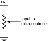
In Figure 2, you use a potentiometer, which is a variable resistor with three connections. The center of the potentiometer, called the wiper, is connected to the microcontroller. The other two sides are attached to power and ground. The wiper can move from one end of the resistor to the other. In effect, it divides the resistor into two resistors and measures the resistance at the point where they meet, just like a voltage divider.
Related videos:
Since a microcontroller’s inputs can read only two values (typically 0 volts or the controller’s supply voltage), an analog input pin needs an extra component to read this changing, or analog voltage, and convert it to a digital form. An analog-to-digital converter (ADC) is a device that does this. It reads a changing input voltage and converts it to a binary value, which a microcontroller can then store in memory.Many microcontrollers have ADCs built in to them. Arduino boards have an ADC attached to the analog input pins.
The ADC in the Arduino can read the input voltage at a resolution of 10 bits. That’s a range of 1024 points. If the input voltage range (for example, on the Uno) is 0 to 5 volts, that means that the smallest change it can read is 5/1024, or 0.0048 Volts. For a 3.3V board like the Nano 33 IoT, it’s 0.0029 volts. When you take a reading with the ADC using the analogRead() command, the microcontroller stores the result in memory. It takes an int type variable to store this, because a byte is not big enough to store the 10 bits of an ADC reading. A byte can hold only 8 bits, or a range from 0 to 255.
The command in Arduino is the analogRead() command, and it looks like this:
sensorReading = analogRead(pin);
- Pin is the analog input pin you are using;
- sensorReading is an integer variable containing the result from the ADC.
The number produced in sensorReading is will be between 0 and 1023. Its maximum may be less, depending on the circuit you use. A potentiometer will give the full range, but a voltage divider for a variable resistor like a force sensing resistor or flex sensor, where one of the resistors is fixed, will not.
The analog inputs on an Arduino (and in fact, on most microcontrollers), are all connected to the same ADC circuit, so when the microcontroller has to switch the ADC’s input from one pin to another when you try to read two pins one after another. If you read them too fast, you can get unstable readings. You can also get more reliable readings by introducing a small delay after you take an analog reading. This allows the ADC time to stabilize before you take your next reading.
Here’s an example of how to read three analog inputs with minimal delay and maximum stability:
 sensorOne = analogRead(A0);
 delay(1);
 sensorTwo = analogRead(A1);
 delay(1);
 sensorOne = analogRead(A2);
 delay(1);
Analog and digital inputs are the two simplest ways that a microcontroller reads changing sensor voltage inputs. Once you’ve understood these two, you’re ready to use a variety of sensors.