Introduction
This is an introduction to basic digital input and output on a microcontroller. In order to get the most out of it, you should know something about the following concepts. You can check how to do so in the links below:
These videos will help in understanding digital inputs and outputs:
Digital Inputs
When you’re trying to sense activity in the physical world using a microcontroller, the simplest activities you can sense are those in which you only need to know one thing about the physical world: Whether something is true or false. Is the viewer in the room or out? Are they touching the table or not? Is the door open or closed? In these cases, you can determine what you need to know using a digital input, or switch.
Digital or binary inputs to microcontrollers have two states: off and on. If voltage is flowing, the circuit is on. If it’s not flowing, the circuit is off. To make a digital circuit, you need a circuit, and a movable conductor which can either complete the circuit, or not.
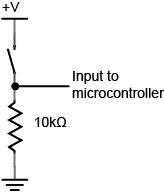
Figure 1 shows the electrical schematic for a digital input to a microcontroller. The current has two directions it can go to ground: through the resistor or through the microcontroller. When the switch is closed, the current will follow the path of least resistance, to the microcontroller pin, and the microcontroller can then read the voltage. The microcontroller pin will then read as high voltage or HIGH. When the switch is open, the resistor connects the digital input to ground, so that it reads as zero voltage, or LOW.
On an Arduino module, you declare the pin to be an input at the top of your program. Then you read it for the values 1 (HIGH) or 0 (LOW), like so:
void setup() {
 // declare pin 2 to be an input:
 pinMode(2, INPUT);
 declare pin 3 to be an output:
 pinMode(3, OUTPUT);
}

void loop() {
 // read pin 2:
 if (digitalRead(2) == 1) {
   // if pin 2 is HIGH, set pin 3 HIGH:
   digitalWrite(3, HIGH);
 } else {
   // if pin 2 is LOW, set pin 3 LOW:
   digitalWrite(3, LOW);
}
Digital output
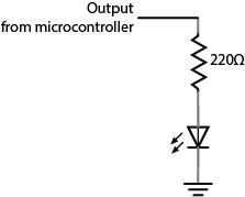
Just as digital inputs allow you to sense activities which have two states, digital or binary outputs allow you to control activities which can have two states. With a digital output you can either turn something off or on. Figure 2 is the schematic diagram for digital output controlling an LED:
Digital outputs are often used to control other electrical devices besides LEDs, through transistors or relays. For more information on that, see these notes on controlling high-current circuits.
On an Arduino module, you declare the pin an output at the top of the program just like you did with inputs. Then in the body of the program you use the digitalWrite() command with the values HIGH and LOW to set the pin high or low, as you’ve seen above.
Here’s a simple blinking LED program in Arduino:
void setup() {
  pinMode(13, OUTPUT);
}

void loop() {
  digitalWrite(13, HIGH);
  delay(1000);
  digitalWrite(13, LOW);
  delay(1000);
}
As inputs, the pins of a microcontroller can accept very little current. Likewise, as outputs, they produce very little current. The electrical signals that they read and write are mainly changes in voltage, not current. When you want to read an electrical change that’s high-current, you limit the current input using a resistor. Similarly, when you want to control a high-current circuit, you use a transistor or relay, both of which allow you to control a circuit with only small voltage changes and minimal current. Related video: Transistor