Introduction
Related video: High Current Loads
When you’re using microcontrollers, you frequently need to control devices that need more electrical current than a microcontroller can supply. Common examples include:
- Controlling a DC motor
- Controlling low-voltage (12-24V) lights
- Controlling addressable LEDs
For all of these applications, you’ll need a high-current power supply. For some applications where the load operates at a voltage higher than your microcontroller but less than your power supply, you’ll need a voltage regulator and to set up your circuit to power the microcontroller and the load through it. For many of these applications, you’ll also need an electrical relay or transistor to control the load. These notes explain relays and transistors as they’re used for this purpose. In order to get the most out of these notes, you should know something about how electricity works, and you should know the basics of how a microcontroller works as well.
Relays
Related video: Relays
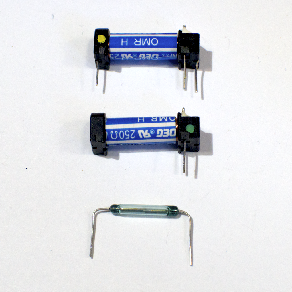
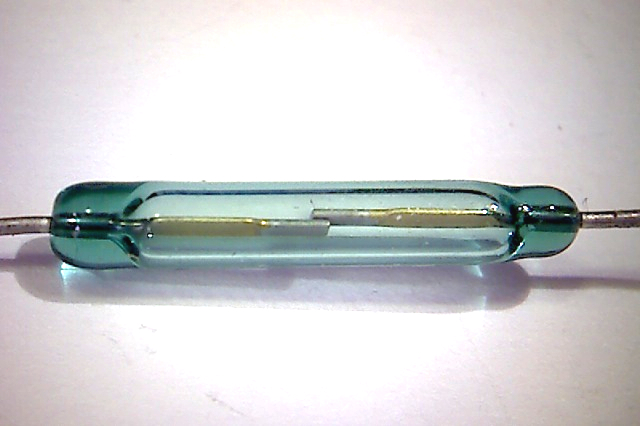
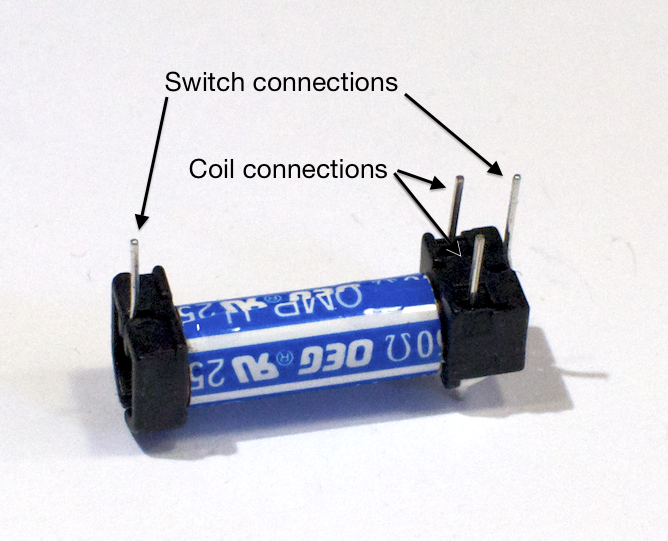
Digital output from a microcontroller is typically a low-amperage signal. For example, when you set a pin HIGH, the voltage coming on that pin is typically +3.3V or +5V, and the amperage that it can source is around 10 milliamps. This is fine if you’re controlling an LED, whose required amperage is tiny. However, most devices you’d want to control need more current than that to operate. You need a component in between your microcontroller and the device that can be controlled with this small voltage and amperage. Relays and transistors are most often used for this purpose. A relay is a switch that’s controlled by a small electric current. Relays take advantage of the fact that when you pass an electric current through a wire, a magnetic field is generated surrounding the wire as well. This is called induction. When you place two pieces of ferrous metal near a coil of wire and pass current through the wire, the magnetic field can move the two pieces of metal towards each other. Those pieces of metal can form a switch, which can be turned on and off by putting current through the coil, as shown in Figure 1, 2 and 3.
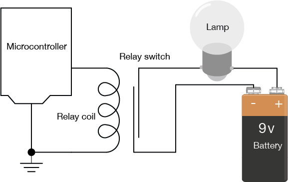
In Figure 4, you can see that there’s no electrical connection between the microcontroller circuit that’s controlling the coil of the relay and the lamp circuit. This is one advantage that relays offer. Figure 5, a schematic of the relay circuit is the same as Figure 4, but shown with traditional schematic symbols for the relay, the battery, and the lamp:
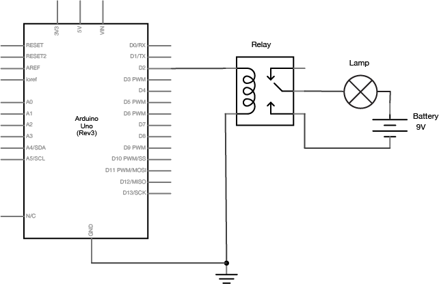
The current needed to move the shaft in the coil is very low (less than 10 milliamps) so the coil can be energized by an output pin of your microcontroller. The current that can flow through the switch, however, is much higher. The lamp circuit is separate from the microcontroller. It uses a separate power source, with the amperage and voltage needed to turn on the lamp. The power source, the lamp, and the switch side of the relay are all placed in series. When the coil is energized, the leaves of the switch are physically moved by the magnetic force created, the lamp circuit is completed, and the lamp turns on.
Because there is no electrical connection between the switch and the coil, relays can also control AC loads as well as DC loads. You can’t use a relay to dim a lamp or control the speed of a motor, however. The switching speed of relays is too slow to pulsewidth modulate them.
Transistors
Related videos: Transistor Schematics, NPN Transistors, PNP Transistors, Darlingtons and MOSFETs
Because a relay is a mechanical switch, it can be somewhat slow. Relays take a few milliseconds to close, so they aren’t very effective when you want to turn them on and off rapidly. Sometimes you need to switch a high current circuit rapidly. In this case you would use a switching transistor. A transistor is an electronic device that can work as a switch. It allows control of a large current by a smaller current as does a relay. Unlike a relay, however, a transistor is not mechanical, and can operate much faster than a relay. There are several types of transistors and they come in two major classes: bipolar transistors, and field-effect transistors, or FETs. All transistors have some similar properties though. They all have three connections, referred to as the base, the collector, and the emitter (on FET transistors, the three connections are the gate, the drain and the source).When you apply a small voltage and current between the base of a transistor and the emitter (or the gate and the drain on a FET), you allow a larger current to flow from the collector to the emitter (or the drain and the source).
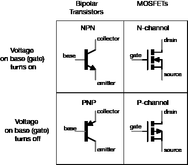
Among bipolar transistors, which are the older class of transistors, there are two types: NPN transistors, and PNP transistors. When you apply positive voltage to the base of an NPN transistor, it turns on the collector-emitter connection and allows current to flow from collector to emitter (Figure 6). The equivalent MOSFET is called an N-channel MOSFET. When you apply voltage to the base of a PNP transistor, by contrast, the collector-emitter connection turns off, and no current can flow from collector to emitter. The MOSFET equivalent is a P-channel MOSFET. One of the main differences between MOSFETS and bipolar transistors is that MOSFETS require negligible current on the base in order to activate. For the purposes of switching a load on and off, they are an excellent choice.
Among the bipolar transistors, there’s one type commonly used to switch high-current loads, the Darlington transistor. Darlington transistors are actually two transistors in one, combined with a diode that protects the transistors from damage in case the load’s current runs in reverse. In many of the labs on this site, you’ll see reference to one the TIP120 Darlington transistor.
Darlington transistors aren’t the only good transistors for high-current loads, though. You could use an N-Channel MOSFET with a protection diode in place of the darlington transistor. The IRF520 MOSFET is a good equivalent if you’re using a 5-volt microcontroller like the Uno. The FQP30N06L MOSFET works well for both 5V microcontrollers and 3.3V microcontrollers like the Nano 33 IoT.
Figure 7 shows the basic circuit for using a transistor to control a high-current load. You connect a DC power source to one terminal of the load, then connect the second terminal of the load to the collector of the transistor (or drain, for a MOSFET) of the transistor. The emitter (or source) is then connected to ground, and the base (or gate) is connected to the output of your microcontroller. When you take the output pin of the microcontroller high, the voltage difference between the base (or gate) and the emitter (or source) allows current to flow through the load, through the collector (or drain) to the emitter (or source) and to ground.
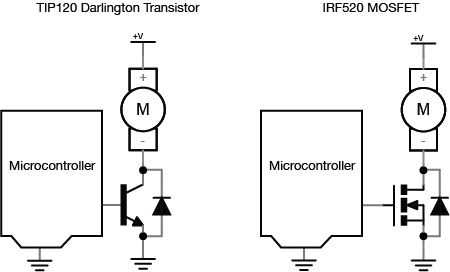
Note how similar this schematic is to the relay schematic. The transistor here is serving the same function as the relay. However, it can switch much faster than the relay. In addition, because there are no mechanical parts, it will reliably function for more switching operations than the relay. However, current can only flow in one direction through a transistor. If the voltage on the collector (or drain) is lower than that on the emitter (or source), you can damage the transistor. The same is not true with a relay.
There are three differences between this transistor circuit and the relay circuit above. The first is that you’re using a motor as the load, rather than an incandescent light bulb. Because motors are inductive loads (they work because of induction; for more, see the DC motor notes), they can create a reverse voltage when spinning down after you turn them off. Because of this, the second difference is the protection diode in parallel with the transistor. The protection diode routes any reverse voltage around the transistor, thereby protecting it. Most transistors designed for controlling motors have a protection diode built-in. The TIP120, the IRF520, and the FQP30N06L all have built-in protection diodes. The third difference is that the microcontroller attached to the base (or gate) and the transistor’s emitter (or source) must have a common ground. If not, then the circuit will not work.
If you are switching DC motors, solenoids, or other high-current DC devices which create motion, it’s better to use a switching transistor than a relay. The ideal way to control a motor is with an H-bridge, which is an array of transistors that lets you control not only speed but also direction. There’s more on that in the motor control notes.