Microcontrollers: The Basics

Overview

Different kinds of computers are designed for different purposes. The computer at the heart of your laptop is optimized for different purposes than the one in your phone or the one in your mouse. The simplest computers are those that are designed to take inout from the physical world and control output devices in the physical world. These are called microcontrollers.

Most electronic devices you use today have a microcontroller at their core. Microcontrollers are optimized for control of physical input and output. They’re generally less computationally capable than the processors used in multimedia computers or servers, for example. They require less power than a those other processors, and they’re easier to interface with the physical world through input circuits called sensors and output circuits called actuators. They can communicate with other processors through various communication interfaces.

Computer, microcontroller, processor? Which is which?

You’ll hear these terms thrown around interchangeably here and in other writing about computers. Computer and processor are generic terms for the anything that can run a program, basically. Controller or microcontroller is usually reserved for a simple processor that does only one task, like listening to sensors. In explaining microcontrollers, we’ll distinguish them from personal computers or servers, which contain more powerful processors that can run an operating system.

Microcontrollers: Computers for the Physical World

When you’re building something that controls digital media from the physical world, it’s common to use microcontrollers to sense the user’s actions, then pass information about those actions to a multimedia processor like the one in your laptop. Keyboards and computer mice have microcontrollers inside that communicate with personal computers using the USB communications protocol.

Atmel Atmega328P chip. This 28 pin chip is the processor for the Arduino Uno
Figure 1.  Atmel Atmega328P chip
Atmel Atmega328P chip in a surface-mount format, designed for robot soldering.
Figure 2. Atmel Atmega328P chip
Surface mount package of the Atmega328. This version is slightly larger than the previous one, but still designed for robot soldering.
Figure 3. SMD package of a microcontroller

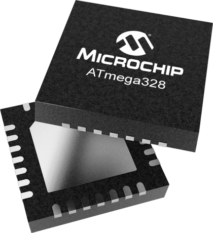
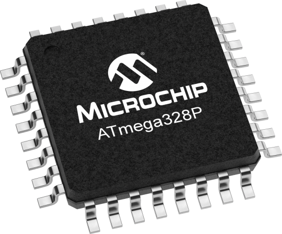
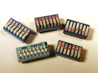
Microcontrollers come in many different size packages as shown in Figure 1,  Figure 2 and Figure 3.

Like any other computer, a microcontroller has to have input ports to detect action by a user, and output ports through which it expresses the results of its programs. The metal pins or contact points on a microcontroller are the inputs and outputs. Other devices, like light, heat, or motion sensors, motors, lights, our sound devices, are attached to these pins to allow the microcontroller to be sensitive to the world and to express itself. A microcontroller also requires power connections and communications connections, just like any other computer.

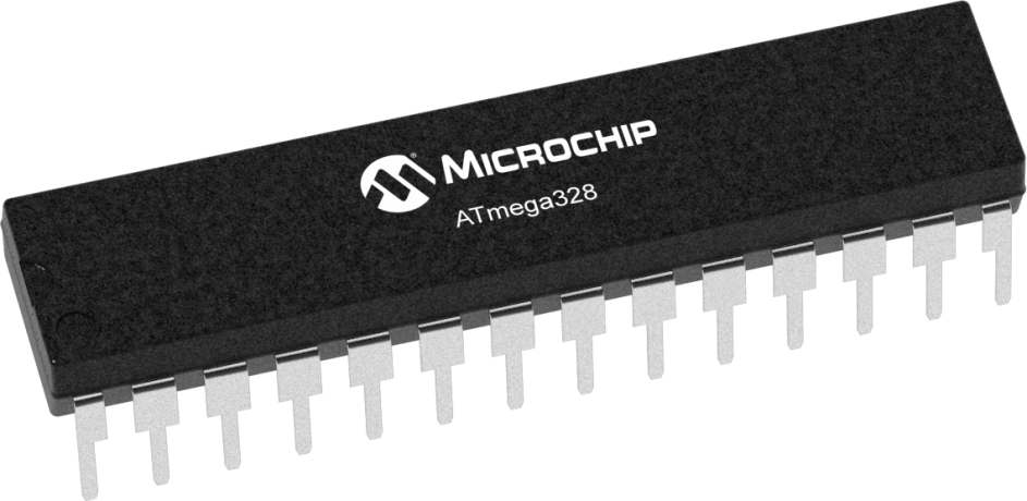
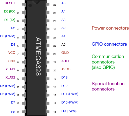
Figure 4 shows an Atmel (now owned by Microchip) microcontroller with its pins labelled. You can see which ones are general purpose input and output (GPIO), which ones are for power and communications, and which ones have specialty functions as well, the most common of which is analog input. For more on the typical functions of a microcontroller, see the Microcontroller Pin Functions page.

ATMEGA328 pin diagram with each pin's location and name
Figure 4. ATMEGA328 pin diagram

There are several different types of microcontrollers. The simplest have very little program memory, only one or two GPIO pins and no specialty functions. These might only cost a fraction of a dollar apiece in large quantities. Slightly more capable ones will have more memory, more GPIO pins and will include specialty functions as well, such as dedicated pins for particular communications protocols. The Atmega328 processor that’s at the heart of the Arduino Uno is one of these processors. The SAMD21 at the heart of the Nano 33 IoT is its more modern cousin. You can buy these processors for a few dollars apiece in quantity. More powerful than those are the controllers that have connections to interface to a display screen, like those in your mobile phone. These might cost several dollars, or tens of dollars. The more memory, processing power and input/output ports that a microcontroller has, the more expensive it tends to be.

When your device is complex enough to need an operating system, it might contain several controllers and processors. The controls for displays, power, and physical I/O are usually farmed out to microcontrollers, while the central processor runs the operating system, communicating with each lesser processor as needed.

The line between microcontrollers and operating system processors is getting blurry these days, so it helps to understand types of programs that different devices might run in order to understand the difference.

Programs for Microcontrollers and Other Processors

Programs for any processors fall into a few different classes: firmware, bootloaders, basic input-output systems, and operating systems. When you understand how they’re all related, you gain a better picture of how different classes of processors are related as well.

Microcontrollers generally run just one program as long as they are powered. That program is programmed onto the controller from a personal computer using a dedicated hardware programming device. The hardware programmer puts the program on the controller by shifting the instructions onto it one bit at a time, through a set of connections dedicated for this purpose. If you want to change the program, you have to use the programmer again. This is true of any processor, by the way: even the most powerful server or multimedia processor has to have a piece of firmware put on it with a hardware programmer at first.

Microcontrollers generally don’t run operating systems, but they often run bootloaders. A bootloader is a firmware program that lives in a part of the controller’s memory, and can re-program the rest of that memory. If you want to program a microcontroller directly from a personal computer without a separate hardware programmer, or from the internet, then you need a bootloader. Whenever your phone is upgrading its firmware, it’s doing it through a bootloader. Bootloaders allow a processor to accept new programs through more than just the dedicated programming port.

Any processor that runs an operating system will run a Basic Input-Output System, or BIOS as well. A BIOS may be loaded onto a processor using a bootloader. A BIOS runs before, or instead of, the operating system. It can control any display device attached to the processor, and any storage attached (such as a disk drive), and any input device attached as well.

Bootloaders and BIOSes are often called firmware because they’re loaded into the flash memory of the processor itself. See Table 1 for types of firmware. Other programs live on external storage devices like disk drives, and are loaded by the BIOS. These are what we usually think of software. Table 2 shows different kinds of software. When you change a processor’s firmware, you need to stop the firmware from running, upload the new firmware, and reset the processor for the changes to take effect. Similarly, when you change a microcontroller’s program, you stop the program, upload the new one, and reset the microcontroller.

An operating system is a program that manages other programs. The operating system schedules access to the processor to do the tasks that other programs need done, manages network and other forms of communications, communicates with a display processor, and much more.

Programs are compiled into the binary instructions that a processor can read using programs called compilers. A compiler is just one of the many applications that an operating system might run, however. The applications that an operating system runs also live on external storage devices like disk drives.

FirmwareStored OnDetail
Single ProgramProcessor’s program memory Is the only program running; must be loaded by hardware programmer
BootloaderProcessor’s program memoryMust be loaded by hardware programmer; Takes small amount of program memory; can load another program into the rest of program memory
BIOSProcessor’s program memoryUsually loaded by bootloader; can load operating system into RAM memory
Table 1. Types of firmware that are stored directly on a microprocessor

SoftwareStored onDetails
Operating SystemExternal mass storageRuns other programs; loaded into RAM by BIOS; unloaded from RAM on reset
DriversExternal mass storageControls access to other processors, like disk drivers, keyboards, mice, screens, speakers, printers, etc. These are usually loaded into RAM on startup of the OS, and controlled by the OS, not the user.
ApplicationsExternal mass storageLoaded into RAM by operating system and unloaded as needed
Table 2. Types of software on an operating system processor, and where they are stored.

Generally, the term microcontroller refers to firmware-only processor, and a processor that runs an operating system from external storage is called an embedded processor, or a central processor if it’s in a device with lots of other processors. For example, the Arduino is a microcontroller. The Raspberry Pi and BeagleBone Black are embedded processors. Your laptop are multi-processor devices running a central processor, a graphics processor, sound processor, and perhaps others.

Microcontroller Development Boards and Activity Boards

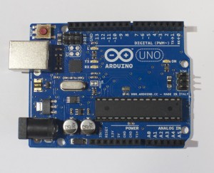
A processor, whether microcontroller or multimedia processor, can’t operate alone. It needs support components. For a microcontoller, you need at least a voltage regulator and usually an external clock called a crystal. You might also add circuitry to protect it in case it’s powered wrong, or in case the wrong voltage and current are plugged into the IO pins. You might include communications interfaces as well. This extra circuitry determines the base cost of a development board like the Arduino (Figure 5) or the Raspberry Pi (Figure 6).

Development boards usually include:

  • The processor itself
  • Power regulation circuitry
  • Hardware programmer connector
  • Communications interface circuitry
  • Basic indicator LEDs
An Arduino Uno. The USB connector is facing to the left, so that the digital pins are on the top of the image, and the analog pins are on the bottom.
Figure 5. An Arduino Uno.
A Raspberry Pi
Figure 6. A Raspberry Pi

More advanced development boards might also include multiple communications interface circuits, including wireless interfaces; sensors already attached to some of the GPIO pins; a mass storage connector like an SD card; and video or audio circuitry, if the processor supports that. The more features a board offers, the more it costs.

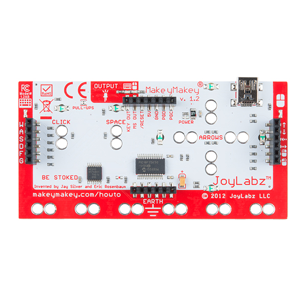
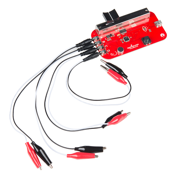
A development board allows you to program the controller’s firmware and software, but an activity board may not. Activity boards contain a pre-programmed microcontroller and some sensors and actuators along with a communications interface and a communications protocol so that you can interface the board and its sensors and actuators with software running on your personal computer. Boards like the MaKey MaKey (Figure 7) or the PicoBoard (Figure 8, now retired) are activity boards. Activity boards generally can’t operate on their own without being connected to a personal computer, while development boards can.

A Makey Makey Board
Figure 7. A Makey Makey Board
A Sparkfun Picoboard
Figure 8. A Sparkfun Picoboard

Do I Really Need A Development Board?

You can buy and program microcontrollers without a development board or activity board, but you’ll need some extras to do so. First, you’ll need to design your own support circuitry, at least a programmer interface and a power supply. You’ll need a hardware programmer as well, in most cases. And you’ll need to buy breakout boards or learn to make very small surface-mount circuits, since fewer and fewer microcontrollers come in the large dual inline package (DIP) that can plug into a solderless breadboard anymore. Generally, until you are very comfortable with electronics and circuit fabrication, it’s best to start with an activity board or a development board.

Toolchains and Development Environments

The two most common languages for microcontrollers are the assembly language of each particular processor, or the C programming language.  More modern processors are starting to be developed in Python as well. A toolchain is the combination of compilers and  linkers needed to convert the instructions you write into a binary file that the microcontroller can interpret as its instructions and the programmer software needed to upload that into the processor.  Every manufacturer and processor family has its own assembly language (the beginning of the toolchain), but there’s a C compiler for almost every microcontroller on the market. Beyond that, a toolchain might include a compiler or firmware to convert a higher level language into the controller’s assembly language. If it’s a scripted language like Python, then the microcontroller’s firmware might include a Python interpreter that remains on the controller as your various scripts are swapped for one another in development.

A toolchain does the work of converting your code, but an integrated development environment (IDE) is needed to connect you, the programmer, to the toolchain. An IDE usually contains a text editor with user interface elements to send your text to the toolchain and upload the result to the processor. IDEs will also include a display to give you error messages about your code, and a monitor of some sort so that you can see what your code does when it’s running on the processor.

Things to consider when picking a microcontroller:

Here’s a guide to picking a microcontroller for this class. What follows are the economic considerations for picking a microcontroller more generally.

Costs

How much do I want to spend? The more features and flexibility, the higher the cost. But if it reduces the time taken between setting up and expressing yourself, it may be worth spending the extra money.

Time

How much work do I want to do?

An activity board or higher level development board will generally minimize the amount of work you do to build your interface to the world. Lower level dev boards or building your own boards will take more work before you have things working. Don’t go build your own boards unless you have to. Many good projects never get completed on time because the maker wanted to use their project as a way to learn how to make a circuit.

What programming languages/communications protocols/electronics do I already know?

All other things being equal, pick a system whose components you know something about.

What’s the knowledge base like?

Most microcontrollers have several websites and listserves dedicated to their use and programming. Quite often, the best ones are linked right off the manufacturer’s or distributor’s website. Check them out, look at the code samples and application notes. Read a few of the discussion threads. Do a few web searches for the microcontroller environment you’re considering. Is there a lot of collected knowledge available in a form you understand? This is a big factor to consider. Sometimes a particular processor may seem like the greatest thing in the world, but if nobody besides you is using it, you’ll find it much harder to learn.

Expandability/Compatibility

What other components is the microcontroller compatible with?

Can you add on modules to your microcontroller? For example, are their motor controllers compatible with it? Display controllers? Sensors or sensor modules? Often these modules are expensive but they just snap into place without you making any special circuitry. If your time is worth a great deal, then these modules are a good buy. Sometimes even if you know how to build it with a lower level controller, a higher level system is worth the cost because it saves building and maintenance time.

What do I have to connect to?

Are you connecting to a MIDI synthesizer? A DMX-512 lighting board? A desktop computer? The phone system? The Internet? Different microcontrollers will have different interface capabilities. Make sure you can connect everything together. Sometimes this requires some creative combinations of controllers if no one controller can speak to all the devices you want it to speak to.

Physical and Electrical Characteristics

How many inputs/outputs do I need? Every system has a certain number of ins and outs. If you can, decide how many things you want to sense or control before you pick your controller.

What kinds of inputs and outputs do I need? Do you need analog inputs and outputs, for sensing changing values, or do you only need digital ins and outs, for sensing whether something is on or off? Most of the embedded Linux boards (for example, the Raspberry Pi) do not have analog inputs, so be careful of that.

What kind of power is available to me? Does it need to be battery powered? Does it need to match the voltage of another device? Does it need to draw very little amperage?

How fast do I need to process data? Lower level processors will generally give you more speed.

How much memory do I need? If you’re planning some complex data processing or logging, you may need a microprocessor with lots memory, or the ability to interface with external memory.

How small does it need to be? A lower level controller generally lets you build your own circuitry, allowing you to reduce the size of the hardware you need.

The Economics of Microcontroller Development

So where does this leave you, the hobbyist or beginner with microcontrollers? What should you choose?

Using mid-level microcontrollers will cost you relatively little up front, in terms of peripherals. The various components you’ll need to make a typical project will run you about $75 – $100, including the controller. Starter kits are a good investment if you’ve never done it before, as they get you familiar with the basics. If you know your way around a circuit, you can start with just a development board. You can always keep the project intact and re-use the microcontroller for other projects. You’ll save yourself time not having to learn how a hardware programmer works, or which compiler to choose, or how to configure it. For the beginner seeking immediate gratification, mid-level is the way to go. The only downside is that if you want to build many more projects, you’ve got to buy another development board.

Using the controllers by themselves, on the other hand, is more of a hassle up front. You’ve got to know how to build the basic support and communications circuits, how to use a hardware programmer, and how to set up a toolchain. You’ll spend a lot of time early on cursing and wishing you’d bought a development board. The advantage comes a bit later on, once everything’s set up. You’ll eventually save money on development boards, and can make them in any shape you want. It gets better the longer you continue making microcontroller projects. So start with development or activity boards, and move up as your needs demand and knowledge can accommodate.

Variables

Adapted from Variables

Introduction

This tutorial explains how computer programs organize information in computer memory using variables. All computer programming languages use variables to manage memory, so it’s useful to understand this no matter what programming language or computer you’re using. Although the following was written with microcontrollers and physical computing applications in mind, it applies to programming in general.

The programming language examples below use a syntax based on the programming language C. That same syntax is used by many other languages, including Arduino (which is written in C), Java, Processing (which is written in Java), JavaScript, and others.

What Is Computer Memory, Anyway?

A computer’s memory is basically a matrix of switches, laid out in a regular grid, not unlike the switches you see on the back of a lot of electronic gear as shown in Figure 1:

Five DIP Switches
Figure 1. DIP Switches

Each switch represents the smallest unit of memory, a bit.  If the switch is on, the bit’s value is 1. If it’s off, the value is 0. Each bit has an address in the grid. We can envision a grid that represents that memory like this:

bit0bit1bit2bit3bit4bit5bit6bit7
bit8bit9bit10bit11bit12bit13bit14bit15
Table 1. All data that’s stored in computer memory is stored in these arrays of bits.

So if a bit can be only 0 or 1, how do we get values greater than 1?

When you count normally, you count in groups of ten. This is because you have ten fingers. So to represent two groups of ten, you write “20”, meaning “2 tens and 0 ones”. This counting system is called base ten, or decimal notation. Each digit place in base ten represents a power of ten: 100 is 102, 1000 is 103, etc.

Now, imagine you had only two fingers. You might count in groups of two. This is called base two, or binary notation. So two, for which you write “2” in base ten, would be “10” in base two, meaning one group of two and 0 ones. Each digit place in base two represents a power of two: 100 is 22, or 4 in base ten, 1000 is 23, or 8 in base ten, and so forth.

Any number you represent in decimal notation can be converted into binary notation by simply regrouping it in groups of two. Once you’ve got the number in binary form, you can store it in computer memory, letting each binary digit fill a bit of memory.  So the number 238 in decimal notation would be 11101110 in binary notation. The bits in memory used to store 238 would look like this:

27 (128)26 (64)25 (32)24 (16)23 (8)22 (4)21 (2)20 (1)
11101110
Table 2. The bits of the decimal value 238. 238 = 27 (128) + 26 (64) +25 (32) +23 (8) + 22 (4) + 21 (2)

Arranging Memory into Variable Space

Programming languages organize computer memory by breaking the grid of bits up into smaller chunks and labeling them with names.  Those names are called variables, and they refer to a location in the computer’s memory. When you ask for the value of a variable, you’re asking what the states of the switches in that location in memory are.

If you think of your program as a set of instructions, then variables are the words that you use to describe what those instructions act upon.

For example:

” When the user has pushed the button two times… “

For this you need a variable called buttonPushed, and you need to check when it’s equal to 2:

1
if (buttonPushed == 2)

When you want to store a piece of something like the number of times a button’s been pushed in the computer’s memory, you give it a name and a data type, which  states how much memory you intend to use. You usually give it an initial value as well. This is called declaring the variable, and it looks like this:

1
2
3
4
int sensorValue = 234;
byte buttonPushed = 15;
long timeSinceStart = 10324;
boolean isOpen = false;

Data Types

Every variable has a data type. The data type of a variable determines how much of the computer’s memory the variable will occupy.  Different programming languages have different data types. The examples above use data types from the C programming language that Arduino uses.

The first one, int sensorValue, is an integer data type. Ints in C take up 16 bits (32 bits in the 32-bit boards like the Nano 33 IoT), so they can contain 216 different values (or 232). Ints can only contain integers, but they can be positive or negative, so the variable sensorValue above could range from -32,768 to 32,767. That’s a range from -215 to 215, with one bit used to store the plus or minus sign.

The second, buttonPushed, is a byte data type. Bytes take up 8 bits, and can therefore store 28 or 256 different values, from 0 to 255. Bytes in Arduino are unsigned, meaning that they can only be positive numbers.

The third, timeSinceStart is a long integer type, for storing very large values. In this instance, it might be storing the number of milliseconds since your program started, which can get big very quickly. Long ints are signed, and can range from -2,147,483,648 to 2,147,483,647. That’s 232 possible values.

The fourth, isOpen, is a boolean variable.  Booleans can only true or false, and ideally take up just one bit in memory (though most programming languages use a whole byte for convenience).

00000000
11101010
00001111
00000000
00000000
00101000
01010100
0
Table 3. A number of variables stored in a processor’s memory as 1s and 0s.

When you declare a variable, the microcontroller picks the next available address and sets aside as many bits are needed for the data type you declare. If you declare a byte, for example, it sets aside 8 bits. An integer gets 16 bits. A string gets one byte (eight bits) for every character of the string, and a byte to end the string.

What About Fractional Numbers?

The variable types above are all for whole numbers, or integers. But how do you store a number like 3.1415 or 2.7828 or other fractional numbers?  These are called floating-point numbers in the programming world, and they’re a special type of variable called a float.  In Arduino, floats are actually 32-bit numbers, stored in 4 bytes of memory. A few of those bits are used to store the decimal point position.

Depending on the processor you are using, the data types might be different sizes. Table 4 shows the different sizes for the data types on the Uno, an 8-bit processor, and the Nano 22 IoT, a 32-bit processor.

Data TypeUnoNano 33 IoT
byte1 byte1 byte
int2 bytes4 bytes
float4 bytes4 bytes
char1 byte1 byte
long4 bytes4 bytes
short2 bytes2 bytes
double4 bytes8 bytes
bool1 byte1 byte
Table 4. The basic Arduino data types and their relative sizes on the Uno and Nano 33 IoT

Here’s a snippet of code to find out a given data type’s size on an Arduino:

1
Serial.print(sizeof(int));

Replace int above with byte, bool, double, float, long, or the data type whose size you want to know.

Choosing the Right Data Type

How do you know what data type to choose when declaring variables? It depends on two factors: what you’re going to use the variables for, and what functions you plan to use on them. First, consider how likely the numbers you might store are likely to be. For example, if you’re counting button pushes, you’re unlikely to get more than a few hundred in a few minutes, so an int or a byte might be fine. But for a number that might get large, like counting the number of milliseconds since some past event, the number could get very large, so you might need a long int.

Different built-in functions of a programming language will require different data types as parameters, so when you can, use data types that match the functions you plan to use.  For example, if you were using a variable to store the results of Arduino’s millis() function, you should use a long int, because millis() returns that data type.

Doing Math With Variables

When you add, subtract, multiply, or divide with variables in a computer program, the results you get depend on the variable types you used. For example,  if you ran the function below:

1
2
3
int voltage = 5;
int divider = 2;
int newVoltage = voltage / divider;

You might think that newVoltage = 2.5, right? Wrong. Because you used ints, the fractional part is gone, so the result would be 2.  Here’s another:

1
2
byte buttonPushes = 254;
buttonPushes = buttonPushes + 4;

After this, you’d expect that buttonPushes = 258, right? Wrong again!  Because you used a byte, you can’t store a value larger than 255, so when the result is larger than that, the number rolls over to the lowest possible value again. The result would be 2.

Wait, what?

Look at it this way. The highest value you can store in a byte is 255. Therefore, if you try to store 256, it rolls over to 0. 257 rolls over to 1. And 258 rolls over to 2. So 254 + 4 in a byte variable yields 2.  If you used an int instead of a byte, then you’d get the result you expect (258) because an int can hold values larger than 255.

Numeric Notation Systems

There are three notation systems used most commonly in programming languages to represent numbers: binary (base two), decimal (base ten), and hexadecimal (base sixteen). In hexadecimal notation, the letters A through F represent the decimal numbers 10 through 15. Furthermore, there is a system of notation called ASCII, which stands for American Standard Code for Information Interchange, which represents most alphanumeric characters from the romanized alphabet as number values. More on ASCII can be found in the pages on serial communication. For more, see this online table representing the decimal numbers 0 to 255 in decimal, binary, hexadecimal, and ASCII. While you can work mostly in decimal notation, there are times when it’s more convenient to represent numbers in ms other than base 10.

Table 5 shows a few number values in the different bases, and the different notation forms:

Decimal valueHexadecimalBinary
 30x030b11
120x0C0b1100
450x2D0b101101
2340xEA0b11101010
10000x3E80b1111101000
Table 5. A few number values in base 10, and their equivalent values in binary (base 2)

Because the values are all bits in the computer’s memory,  you can use all of these notation systems interchangeably. Here are a few examples:

1
2
3
4
5
if (colorValue == 0xFF); // check to see if the color value is 255
 
// add 5 to 0x90. Result will be 0x95:
int channelNumber = 5;
int midiCommand = 0x90 + channelNumber;

Variable scope

Variables are local to a particular function in your code if they are declared in that function. Local variables can’t be used by functions outside the one that declares them, and the memory space allotted to them is released  when the function ends. Variables are global when they are declared at the beginning of a program, outside all functions. Global variables are accessible to all functions in a the program, and their value is maintained for the duration of the program. Usually you use global variables for values that will need to be kept in memory for future use by other functions, and local variables when you know the value won’t be used outside that function. In general, it’s better to default to local variables when you can, to manage memory more efficiently. Here’s a typical example:

1
2
3
4
5
6
7
8
9
10
11
12
13
14
15
16
int oldButtonPush = 0// global variable
 
void setup() {
   Serial.begin(9600);
}
 
void loop() {
   int buttonPush = digitalRead(3); // local variable
   if (buttonPush != lastButtonPush) {
      // the button changed. Do something here
      // then store the current button push state
      // in the global variable for the next time
      // through the loop:
   oldButtonPush = buttonPush; 
   }
}

In this example, the variable buttonPush is local to the loop function. You couldn’t read it in the setup, or any other function. The variable oldButtonPush, on the other hand, is global, and can be read by any function. In the example above, the local variable is used to read the latest state of a digital input, and then later, the value is put into the global variable so that you can get a new reading and compare it to the old one.

Constants

In addition to variables, every programming language also includes constants, which are simply variables that don’t change. They’re a useful way to label and change numbers that get used repeatedly within your program. For example, imagine you’re writing a program that runs a servo motor. Servo motors have a minimum and maximum pulse width that doesn’t change, although each servo’s minimum and maximum might be somewhat different. Rather than change every occurrence of the minimum and maximum numbers in the program, we make them constants, so we only have to change the number in one place.

You don’t have to use constants in your programs, but they’re handy to know about, and you will encounter them in other people’s programs.

In C and therefore in Arduino, there are two ways you can declare constants. You can use the const keyword, like so:

1
2
const int LEDpin = 3;
const int sensorMax = 253;

Or you can use  define:

1
2
#define LEDPin 3
#define sensorMax 253

Defines are always preceded by a #, and are don’t have a semicolon at the end of the line. Defines always come at the beginning of the program. They actually work a bit like aliases. What happens is that you define a number as a name, and before compiling, the compiler checks for all occurrences of that name in the program and replaces it with the number. This way, defines don’t take up any memory, but you get all the convenience of a named constant. There are several defines in the libraries of the Arduino core libraries, so it’s preferable to use const instead of #define for constants.

For more on variables in Arduino, see the variable reference page.

Analog Input

Introduction

This is an introduction to basic analog input on a microcontroller. In order to get the most out of it, you should know something about the following concepts.  You can check how to do so in the links below:

These video links will help in understanding analog input:

Analog Input

While a digital input to a microcontroller can tell you about discrete changes in the physical world, such as whether the cat is on the mat, or the cat is off the mat, there are times when this is not enough. Sometimes you want to know how fat the cat on the mat is. In order to know this, you’d need to be able to measure the force the cat exerts on the mat as a variable quantity. When you want to measure variably changing conditions like this, you need analog inputs. An analog input to a microcontroller is an input that can read a variable voltage, typically from 0 volts to the maximum voltage that powers the microcontroller itself.

Many transducers are available to convert various changing conditions to changing electrical quantities. There are photocells that convert the amount of light falling on them to a varying resistance; flex sensors that change resistance as they are bent; Force-sensitive resistors (FSRs) that change resistance based on a changing force applied to the surface of the sensor; thermistors that change resistance in response to changing heat; and many more.

Related video: Resistors, variable resistors, and photocells

In order to read these changing resistances, you put them in a circuit and pass a current through them, so that you can see the changing voltage that results. There are a few variations on this circuit. The simplest is called a voltage divider. Because the two resistors are in series voltage at the input to the microcontroller is proportional to the ratio of the resistors. If they are equal, then the input voltage is half the total voltage. So in the circuit in Figure 1, if the variable resistor changes (for example, if it’s a flex sensor being bent), then the voltage at the input changes.  The fixed resistor’s value is generally chosen to complement the variable resistor’s range. For example, if you have a variable resistor that’s 10-20 kilohms, you might choose a 10 kilohm fixed resistor.

analog in schematic
Figure 1. voltage divider with a variable resistor and a fixed resistor

In Figure 2, you use a potentiometer,  which is a variable resistor with three connections. The center of the potentiometer, called the wiper,  is connected to the microcontroller. The other two sides are attached to power and ground. The wiper can move from one end of the resistor to the other. In effect, it divides the resistor into two resistors and measures the resistance at the point where they meet, just like a voltage divider.

Related videos:

potentiometer schematic
Figure 2. potentiometer schematic

Since a microcontroller’s inputs can read only two values (typically 0 volts or the controller’s supply voltage), an analog input pin needs an extra component to read this changing, or analog voltage, and convert it to a digital form. An analog-to-digital converter (ADC) is a device that does this. It reads a changing input voltage and converts it to a binary value, which a microcontroller can then store in memory.Many microcontrollers have ADCs built in to them. Arduino boards have an ADC attached to the analog input pins.

The ADC in the Arduino can read the input voltage at a resolution of 10 bits. That’s a range of 1024 points. If the input voltage range (for example, on the Uno) is 0 to 5 volts, that means that the smallest change it can read is 5/1024, or 0.0048 Volts. For a 3.3V board like the Nano 33 IoT, it’s 0.0029 volts. When you take a reading with the ADC using the analogRead() command, the microcontroller stores the result in memory. It takes an int type variable to store this, because a byte is not big enough to store the 10 bits of an ADC reading. A byte can hold only 8 bits, or a range from 0 to 255.

The command in Arduino is the analogRead() command, and it looks like this:

1
sensorReading = analogRead(pin);
  • Pin is the analog input pin you are using;
  • sensorReading is an integer variable containing the result from the ADC.

The number produced in sensorReading is will be between 0 and 1023. Its maximum may be less, depending on the circuit you use. A potentiometer will give the full range, but a voltage divider for a variable resistor like a force sensing resistor or flex sensor, where one of the resistors is fixed, will not.

The analog inputs on an Arduino (and in fact, on most microcontrollers), are all connected to the same ADC circuit, so when the microcontroller has to switch the ADC’s input from one pin to another when you try to read two pins one after another. If you read them too fast, you can get unstable readings. You can also get more reliable readings by introducing a small delay after you take an analog reading. This allows the ADC time to stabilize before you take your next reading.

Here’s an example of how to read three analog inputs with minimal delay and maximum stability:

1
2
3
4
5
6
sensorOne = analogRead(A0);
delay(1);
sensorTwo = analogRead(A1);
delay(1);
sensorOne = analogRead(A2);
delay(1);

Analog and digital inputs are the two simplest ways that a microcontroller reads changing sensor voltage inputs. Once you’ve understood these two, you’re ready to use a variety of sensors.