In this tutorial, you’ll explore the capabilities of the SparkFun Qwiic Shield for Arduino Nano—a modular shield designed to extend the functionality of the Arduino Nano. This shield enables seamless communication between your microcontroller and various I2c-based peripherals like sensors and some displays. It’s a standard connector type that’s been informally adopted by a few other hardware module manufacturers as well. We’ll cover everything from physical setup and orientation to practical demos using sensors available in the ITP shop.
It’s also worth noting that SparkFun’s Qwiic system is fully compatible with Adafruit’s STEMMA QT ecosystem, which uses the same connector and wiring convention. Beyond SparkFun and Adafruit, other companies such as Pimoroni, Seeed Studio, and Pololu have begun integrating this connector into their I2C sensor and breakout boards as well.
What You’ll Need to Know
Before diving in, you should be comfortable with basic Arduino programming and understand the fundamentals of I2C communication. If you need a refresher, review the I2C Communication Labs for in-depth details.
Things You’ll Need
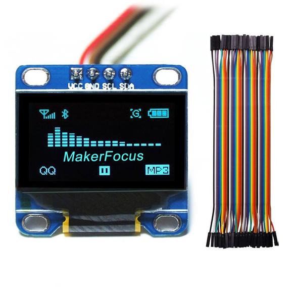
For this tutorial, gather the following components (see Figures 1–6 for reference images):

Shield Orientation and Setup
Physical Orientation
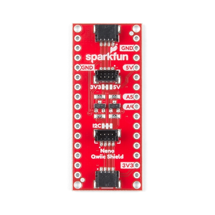
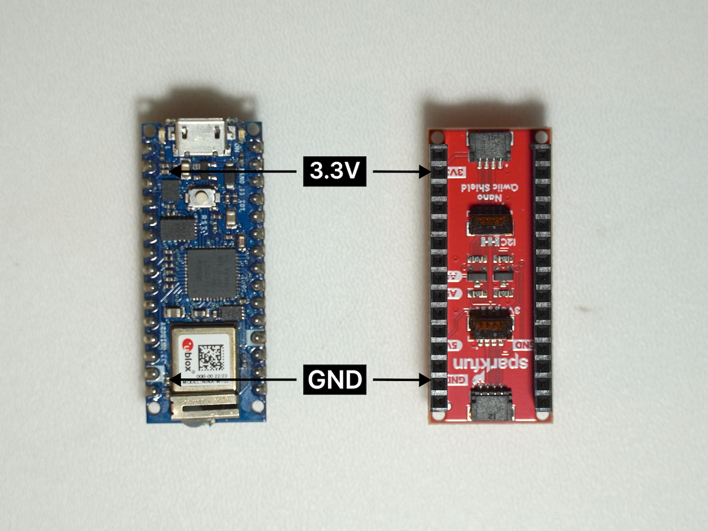
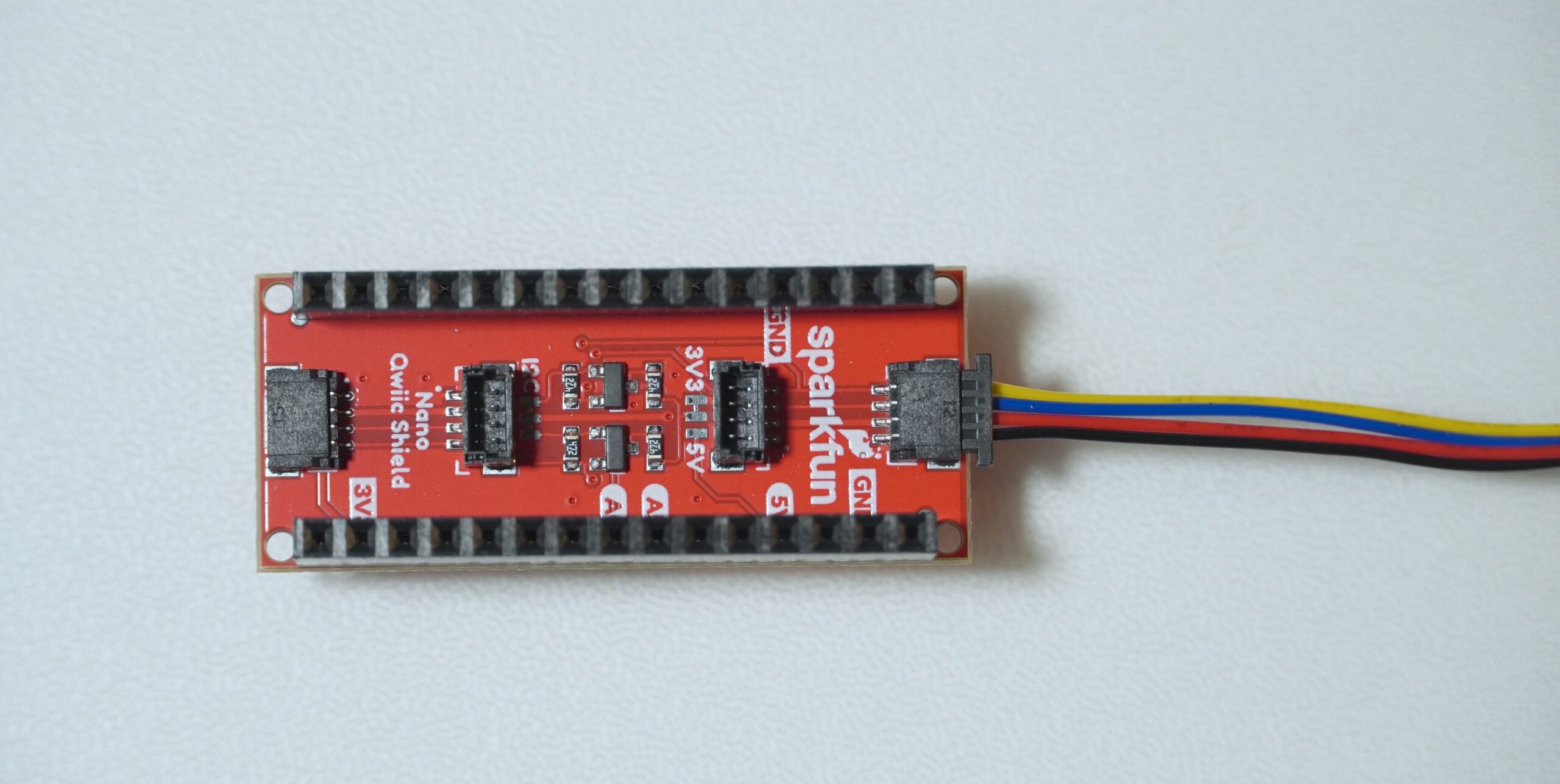
Although the SparkFun Qwiic Shield for Arduino Nano is pinned out exactly like a standard Arduino Nano, it’s still important to verify that you have the correct orientation when mounting the shield. We often reference the 3.3V pin as a quick visual cue to ensure you align everything properly. The shield includes a configurable logic shifting circuit set by the IOREF jumper, which defaults to 3.3V (ideal for boards like the Arduino Nano 33 BLE). If you’re using a 5V Nano variant (such as the Arduino Nano Every), you’ll need to switch the jumper to 5V so that the logic levels match your board’s operating voltage.
The Qwiic shield is designed to be mounted below the Nano with which it’s paired. To mount it below would require reversing the standard pin arrangement on the Nano (they are usually on the side of the board without components) and reversing the sockets on the shield.
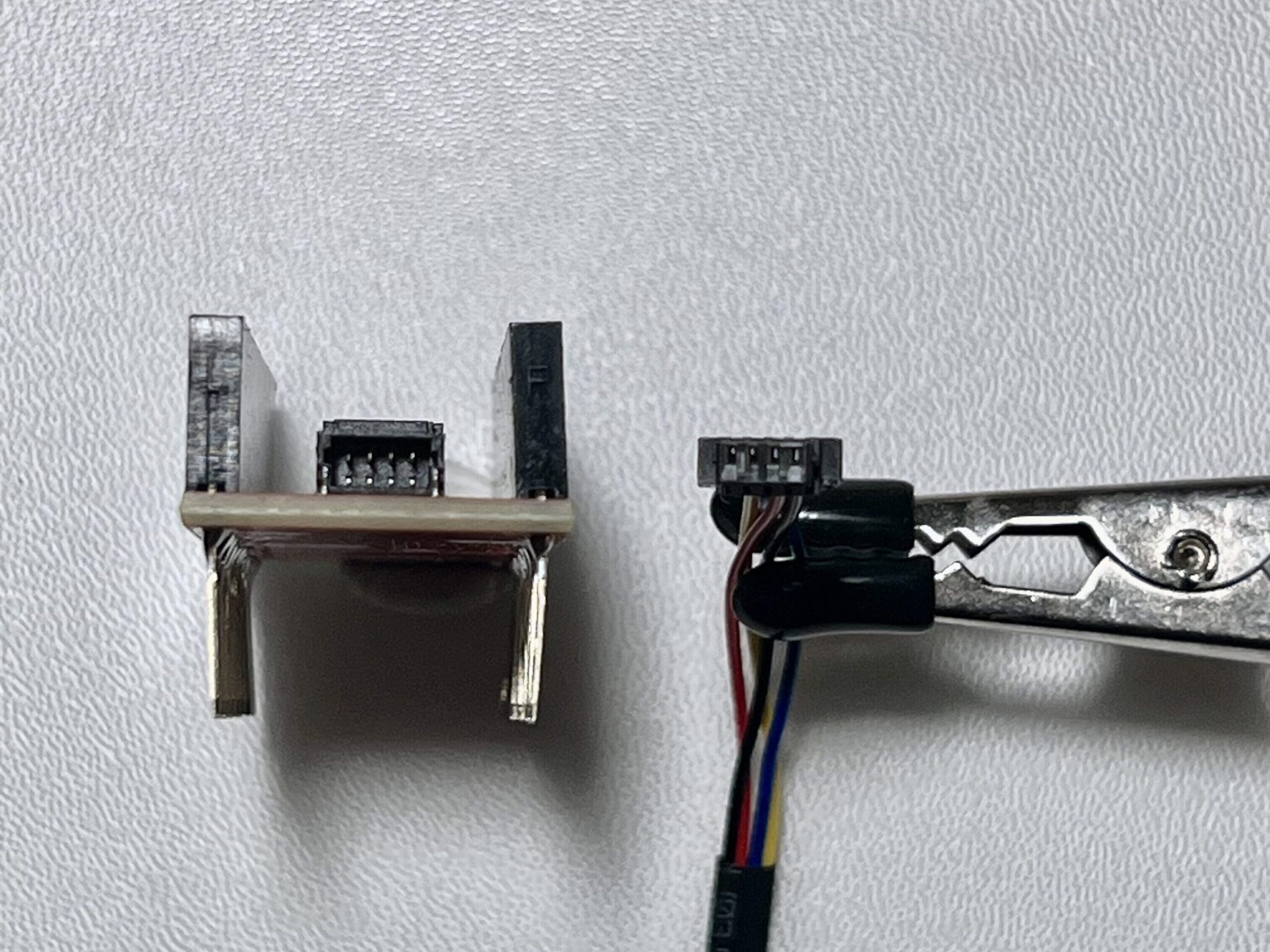
Closer Look at the Adapter
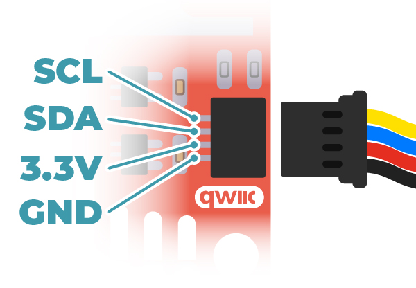
The Qwiic adapter is populated with two 4-pin 1mm JST connectors. These connectors are polarized to prevent incorrect insertion, and the pin order follows the Qwiic standard: GND, 3.3V, SDA, and SCL. When mounting the adapter onto the Nano Qwiic Shield, ensure that the labeled side of the adapter aligns with the corresponding pins on the shield to maintain correct orientation.
Connection Diagram
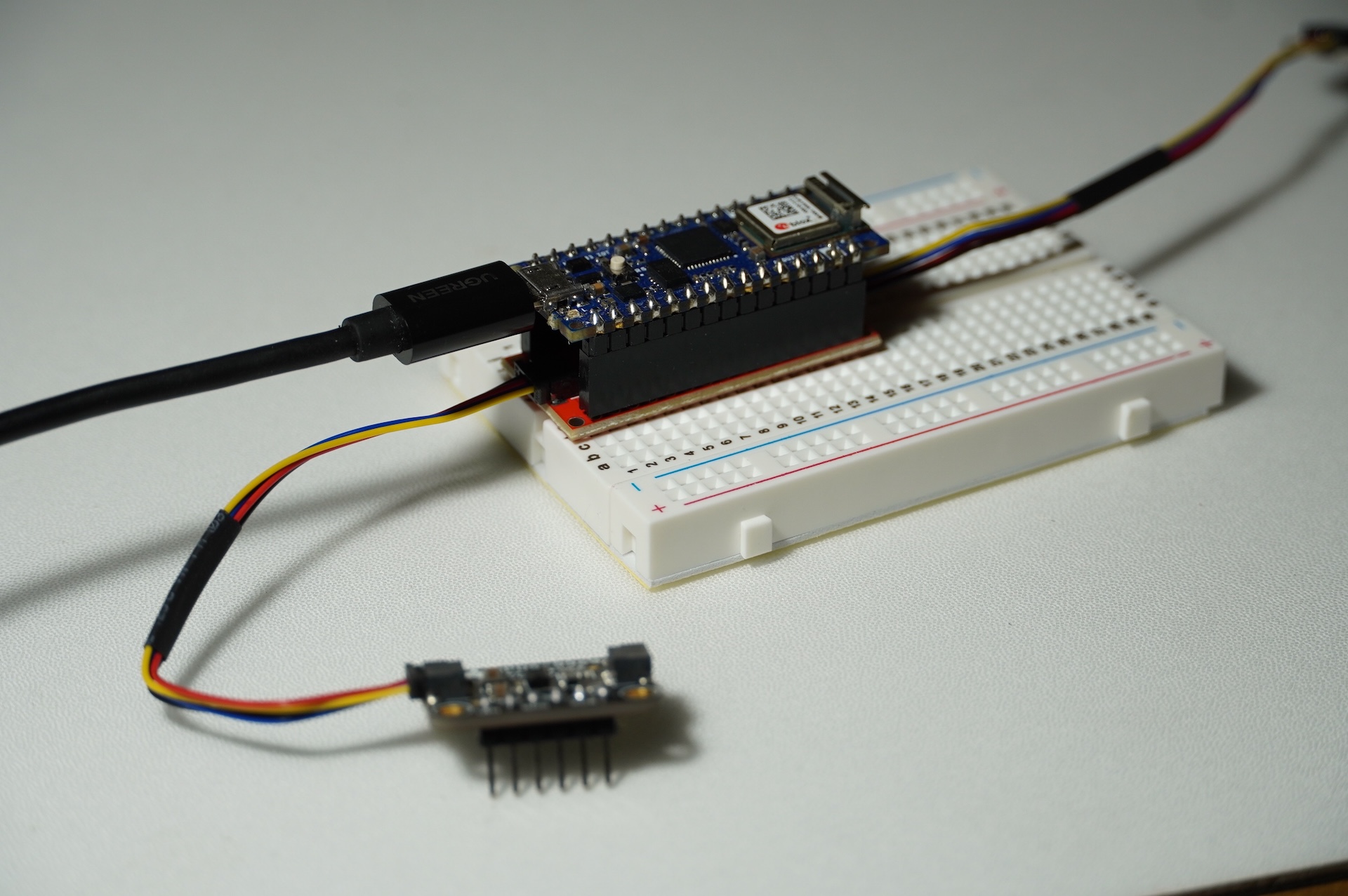
Figure 12 shows the connections between the Qwiic Nano shield and a few typical components.
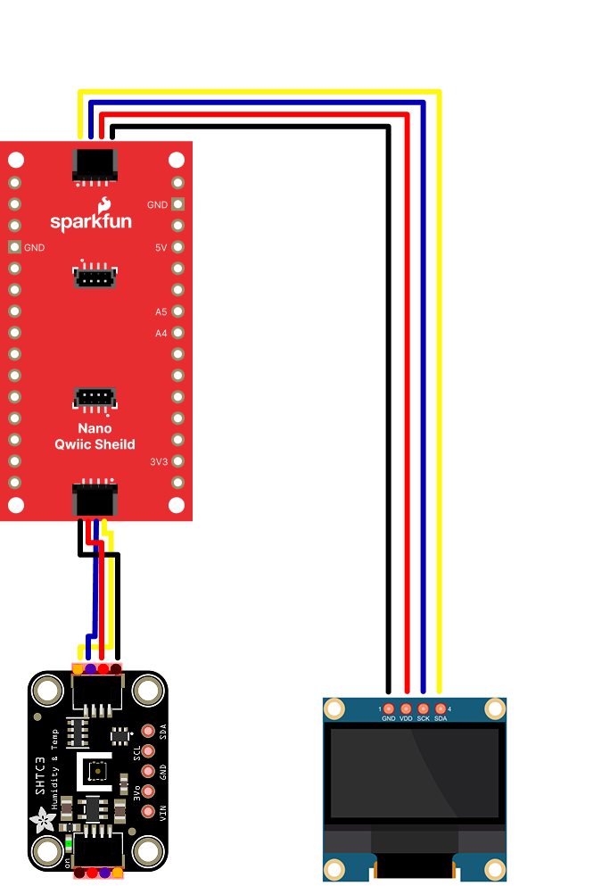
Figure 12. Wiring diagram for a basic Qwiic I2C setup (Arduino below the shield is not shown in this diagram)
Note that while the Arduino Nano is not shown here, it is connected directly on top of the shield. Note also the placement of I2C communication pins (SDA and SCL). Ensuring the correct physical orientation prevents damage and guarantees reliable operation.
I2C Communication Overview
The SparkFun Qwiic Shield leverages the I2C protocol—a standard for connecting multiple devices with just two wires (SDA and SCL). This tutorial assumes that you’ve reviewed the ITP I2C Communication Labs or Related videos: Intro to Synchronous Serial, I2C for background on the protocol.
I2C Basics
- Two-Wire Protocol: Communication occurs over SDA (data) and SCL (clock) lines.
- Device Addressing: Each device on the I2C bus is identified by a unique 7-bit address.
- Pull-up Resistors: These ensure proper voltage levels on the bus and are often integrated on breakout boards.
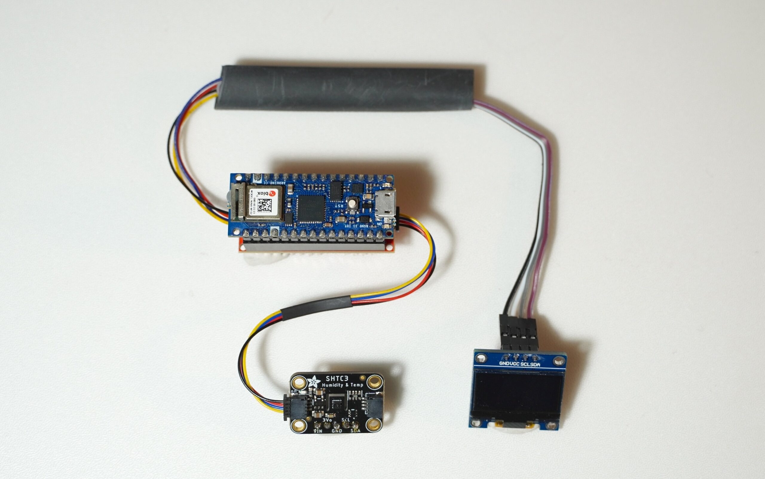
Demo Project: Reading Temperature and Humidity on an OLED Display
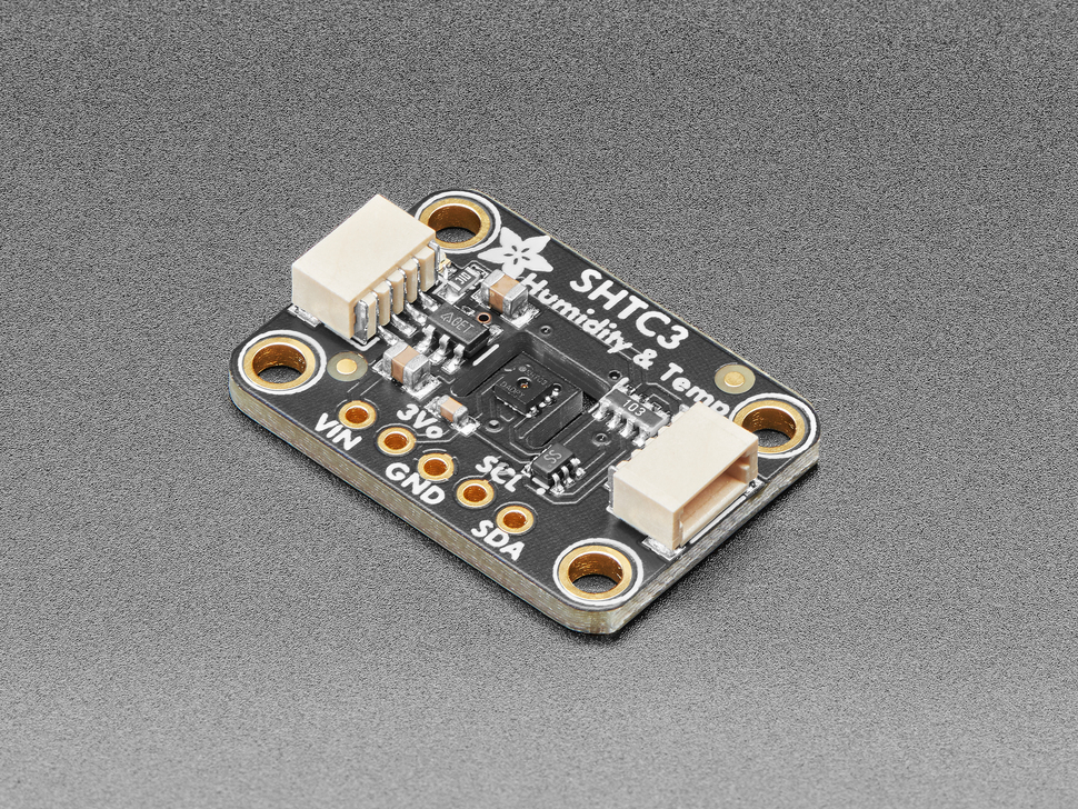
In this project, we’ll read data from SHTC3 (Humidity and Temp Sensor) and display it on an SSD1306 OLED screen. All components communicate via I2C and connect using Qwiic cables—no breadboards or soldering are required.
⚠️ Note: Many I2C sensors from providers like SparkFun (Qwiic) and Adafruit (STEMMA QT) come in two variants:
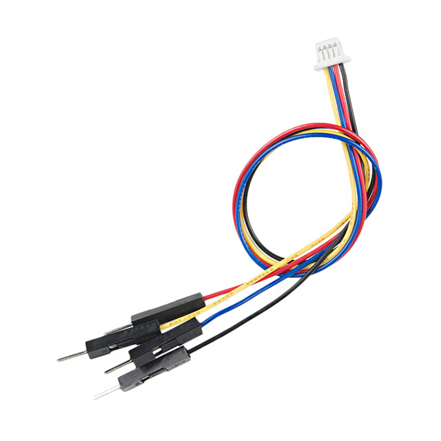
- Qwiic/STEMMA QT-compatible versions, which feature JST connectors for plug-and-play wiring (see Figure 13 below) or
- Standard breakout boards, which expose I2C pins (SDA, SCL, VCC, GND) but require jumper wires or soldering (see Figure 13 below)
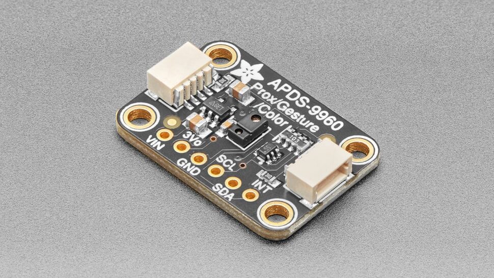
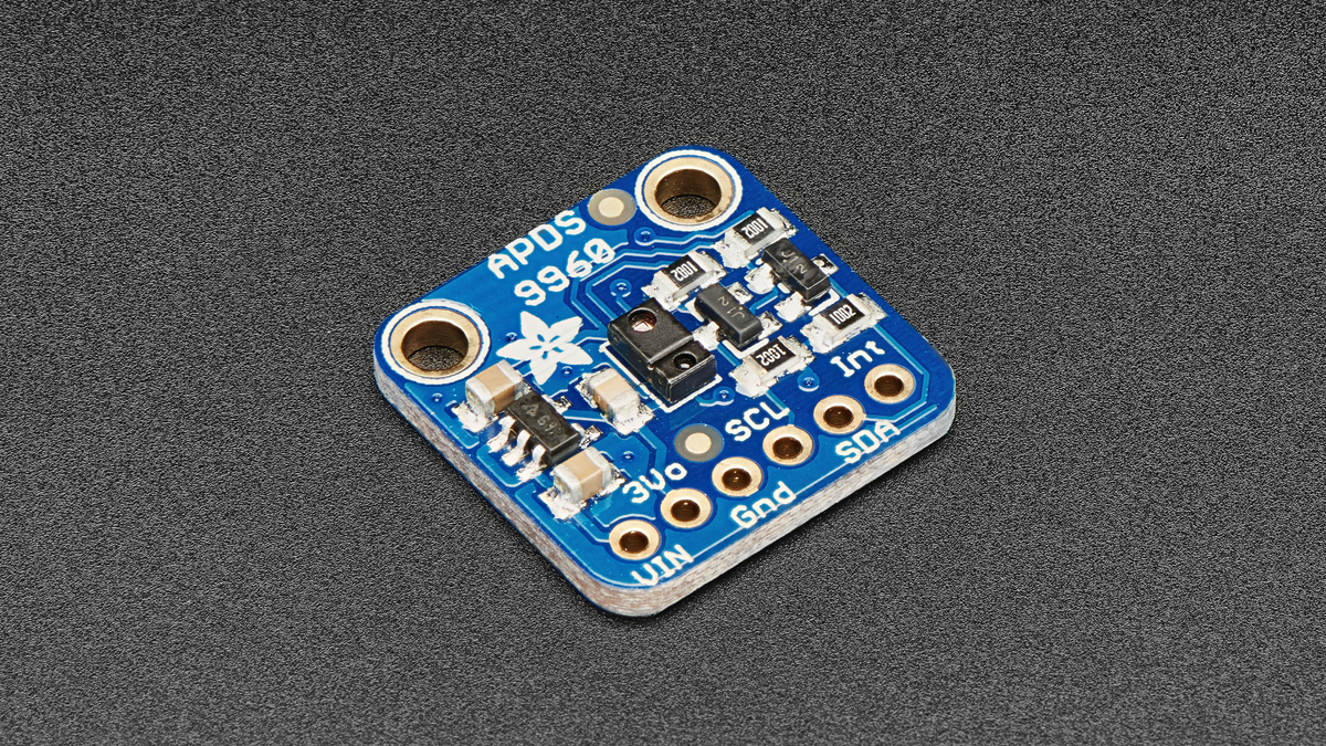
For this demo, we’re using the Qwiic-compatible versions, enabling quick, tool-free connections. However, you can also use standard versions of the same sensors as long as you connect them properly to the corresponding I2C pins.
Hardware Setup
Mount the Shield
- Carefully align the Arduino Nano 33 IoT (or other Nano variant) with the SparkFun Qwiic Shield for Arduino Nano.
- Ensure the 3.3V pins line up correctly to avoid damaging your board.
Connect the Sensors
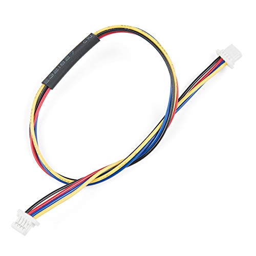
- Connect sensors to any available Qwiic port using Qwiic cables.
- Daisy-chain sensors as needed for project layout.
Attach the OLED Display
- If the OLED display includes a Qwiic connector, directly connect it to a free port or daisy-chain.
- If not, use a Qwiic Jumper Adapter Cable to connect the necessary pins.
Power and Ground
The Nano’s USB port powers the setup, with the Qwiic Shield distributing 3.3V and GND.
Install the External Libraries
In the Arduino IDE’s Library Manager (Sketch > Include Library > Manage Libraries…), install the following libraries and dependencies if needed.
Program the Microcontroller
In the demo code below, we begin by importing the necessary libraries and defining display parameters such as screen size and I2C address. In the setup() function, we initialize both the SHTC3 sensor and the OLED display, and configure display settings including text size, font, and color. In the loop(), the code reads humidity and temperature data from the sensor every three seconds and updates the OLED screen to show the latest values.
// Libraries for sensor and display communication
#include <SPI.h>
#include <Wire.h>
#include <Adafruit_GFX.h>
#include <Adafruit_SSD1306.h>
#include <Adafruit_SHTC3.h>

// Instantiate sensor object
Adafruit_SHTC3 shtc3 = Adafruit_SHTC3();

// OLED display resolution and initialization
#define SCREEN_WIDTH 128
#define SCREEN_HEIGHT 64
#define OLED_RESET -1 // because the reset pin on the OLED is not being used
#define SCREEN_ADDRESS 0x3C
Adafruit_SSD1306 display(SCREEN_WIDTH, SCREEN_HEIGHT, &Wire, OLED_RESET);

void setup() {
  // initialize serial communication
  Serial.begin(9600);
  // wait 3 seconds if the serial monitor is not open:
  if (!Serial) delay(3000);

  // Initialize SHTC3 sensor, loop indefinitely if this fails:
  if (!shtc3.begin()) {
    Serial.println("Couldn't find SHTC3");
    // stop forever if the sensor is not available:
    while (true);
  }
  Serial.println("Found SHTC3 sensor");

  // Initialize OLED display, halt program if allocation fails
  if (!display.begin(SSD1306_SWITCHCAPVCC, SCREEN_ADDRESS)) {
    Serial.println(F("Couldn't find SSD1306 screen"));
    // stop forever if the display fails:
    while (true);
  }

  // Configure display settings
  display.setTextSize(1);
  display.setTextColor(SSD1306_WHITE);
  display.cp437(true);
}

void loop() {
  // make instances of the sensor elements from the sensor library:
  sensors_event_t humidity, temp;

  // Get fresh data from sensor
  shtc3.getEvent(&humidity, &temp);

  // Clear OLED display and set cursor to start
  display.clearDisplay();
  display.setCursor(0, 0);

  // Display temperature readings
  display.println("Temperature: ");
  display.print(temp.temperature);
  display.println(" °C");
  display.println("");

  // Display humidity readings
  display.println("Humidity: ");
  display.print(humidity.relative_humidity);
  display.println("% rH");

  // Update display with new data
  display.display();

  // Wait for 3 seconds before refreshing
  delay(3000);
}
Final Result
Figure 16. Real-time environmental monitoring demo using an Arduino Nano with SparkFun’s Qwiic Shield. The SHTC3 sensor measures temperature and humidity, displaying live data on the SSD1306 OLED screen
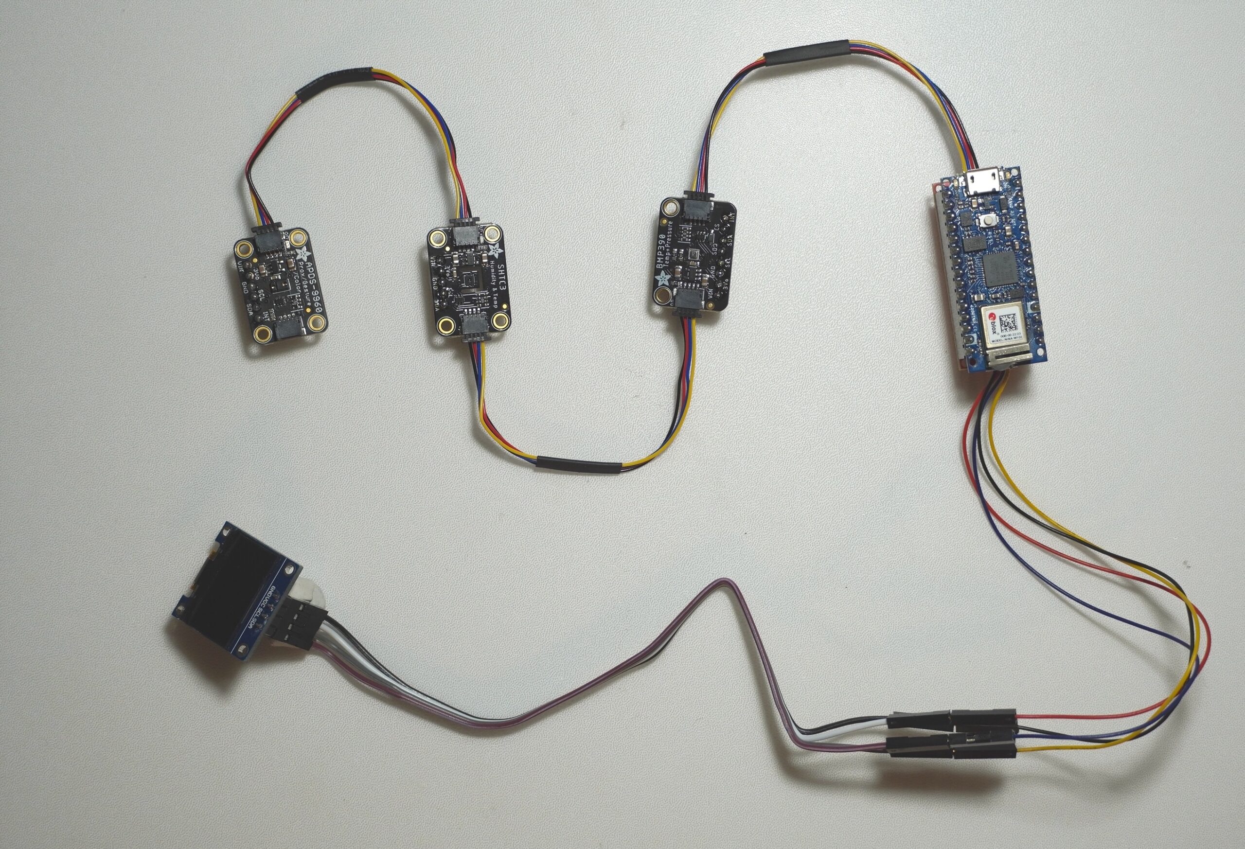
Further Use Cases
For a more advanced setup, we can expand the I2C chain by adding more sensors or devices. In the demo below, there is an APDS-9960 gesture sensor and a BMP388 pressure sensor alongside the SHTC3 temperature and humidity sensor. The user can change the data display on the screen by simple hand movement. You can find examples for these sensors at this link.
Conclusion
The Sparkfun Qwiic Shield can simplify sensor integration and communication with Arduino Nano variants. It’s not the only way to connect IC components, but if you are, and if you’re using a Nano, it’s a handy tool. Whether you’re building a simple temperature monitor or a more complex interactive installation, understanding the practicalities of shield orientation, I2C communication, and connection strategies is key.