Introduction
In this lab, you’ll build an alternative computer keyboard using any of the USB-native boards (Nano 33 IoT, the MKR series, the Due, the Leonardo, the Micro, and the Feather M0 series all fit this requirement). You’ll also learn some techniques for determining when a user takes a physical action. In the Digital Lab and Analog Lab, you learned how to read the input from a digital or analog input, but you didn’t learn how to interpret the stream of data as an event. There are a few everyday physical interactions that are fairly easy to pick out from a stream of data. You’ll see a few of them in this lab.
What You’ll Need to Know
To get the most out of this lab, you should be familiar with the following concepts. You can check how to do so in the links below:
- Digital Input with Arduino
- Analog Input with Arduino
- What is an Arduino Library
- You may also want to try the Sensor Change Detection Lab before this one.
Things You’ll Need
Figures 1-5 show the parts you’ll need for this exercise. Click on any image for a larger view.


About Keyboard control
NOTE: The sketches contained in this lab will cause the microcontroller to take control of your keyboard. Make sure they’re working properly before you add the keyboard commands. The example doesn’t introduce the Keyboard commands until the end of the lab. Instead, messages are printed to the serial monitor to tell you what should happen. When you’ve run this and seen the serial messages occurring when you think they should, then you can add the mouse commands safely.
The circuit diagrams below show an Arduino Leonardo, but you can use any USB-capable board that you wish.
Note on Mouse, Keyboard, and Serial Ports
The Mouse and Keyboard libraries on the SAMD boards (MKRZero, MKR1xxx, Nano 33IoT) have an unusual behavior: using them changes the serial port enumeration. When you include the Keyboard library in a sketch, your board’s serial port number will change. For example, on MacOS, if the port number is /dev/cu.usbmodem14101, then adding the Keyboard library will change it to /dev/cu.usbmodem14102. Removing the Keyboard library will change it back to /dev/cu.usbmodem14101. Similarly, if you double-tap the reset button to put the board in bootloader mode, the serial port will re-enumerate to its original number.
Windows and HID Devices
You may have trouble getting these sketches to work on Windows. On Windows, the default Arduino drivers must be uninstalled so the system can recognize the Arduino as both serial device and HID device. Read this issue and follow the instructions there.
Recovering From a Runaway HID (Mouse or Keyboard) Sketch
Programs which control your keyboard and mouse can make development difficult or impossible if you make a mistake in your code. If you create a mouse or keyboard example that doesn’t do what you want it to, and you need to reprogram your microcontroller to stop the program, do this:
Open a new blank sketch.
This sketch is your recovery:
void setup() {

}
void loop() {

}
Programming the board with this blank sketch removes your mistaken sketch and gives you control again. To do this, however, you need the current sketch to stop running. So:
Put the microcontroller in bootloader mode and upload the blank sketch
On the SAMD boards, you can do this by double-tapping the reset button. The on-board LED will begin glowing, and the bootloader will start so that you get a serial port enumeration, but the sketch won’t run. On the Leonardo and other 32U4-based boards, hold the reset down until you’ve given the upload command. The 32U4 bootloader will take a few seconds before it starts the sketch, so the uploader can take command and load your blank sketch.
Once you’ve got the blank sketch on the board, review the logic of your mistaken Keyboard or Mouse sketch and find the problem before uploading again.
Prepare the breadboard
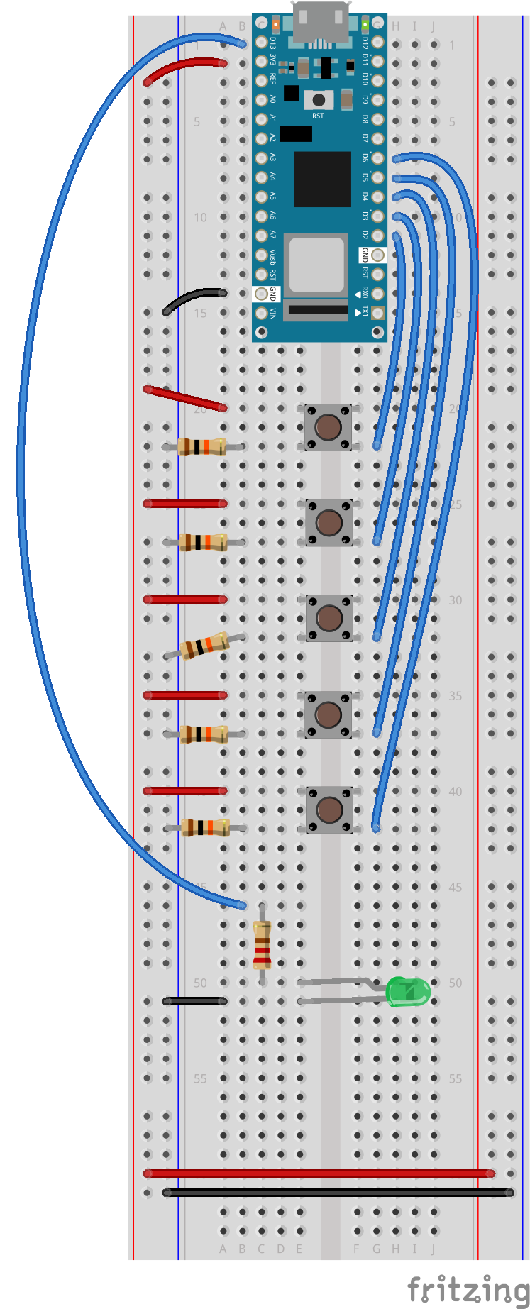
Connect power and ground on the breadboard to power and ground from the microcontroller. On the Arduino module, use the 5V and any of the ground connections as shown below in Figure 7. If using the Arduino Nano connect the 3.3V and ground pins according to Figure 8.
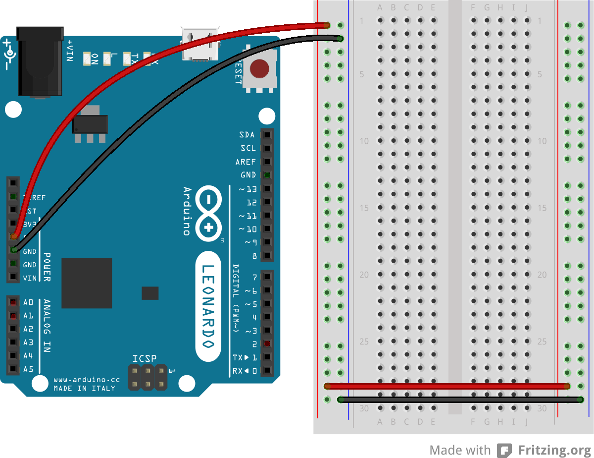

Figure 8. Breadboard view of an Arduino Nano connected to a breadboard. The +3.3 volts and ground pins of the Arduino are connected by red and black wires, respectively, to the left side rows of the breadboard. +3.3 volts is connected to the left outer side row (the voltage bus) and ground is connected to the left inner side row (the ground bus). The side rows on the left are connected to the side rows on the right using red and black wires, respectively, creating a voltage bus and a ground bus on both sides of the board.
Made with Fritzing
Add Several Pushbuttons
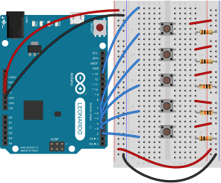
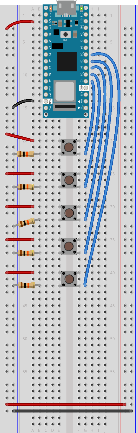
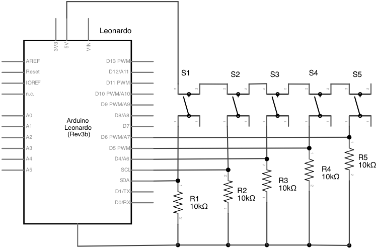
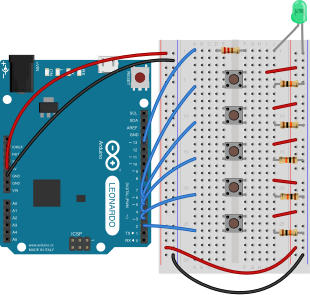
Attach pushbuttons to digital pin 2 through 6 as shown below in Figure 9. For Arduino Nano connections, see Figure 10. For the schematic view, see Figure 11. Connect one side of each pushbutton to voltage, and the other side of the pushbuttons to 10-kilohm resistors. Connect the other end of each resistor to ground. Connect the junction where each pushbutton and resistor meet to a digital pin, using pins 2 through 6. (For more on this digital input circuit, see the Digital Input Lab).
Add an LED
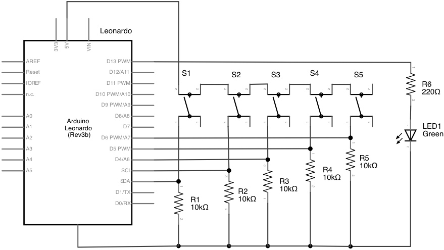
Add an LED and 220-ohm resistor on pin 13 as shown below in Figure 12. For Arduino Nano see Figure 13. For the schematic view, see Figure 14. You’ll use this to keep track of the state of the keyboard control.
In the Sensor Change Lab, you learned how to detect the state change of a digital input. You’ll use the same technique here.
You’ll use the pushbutton on pin 2 to track whether the microcontroller is acting as a keyboard or not. Pressing this button will change the state of a global variable called keyboardIsActive. It will also call the Keyboard.begin() and Keyboard.end() commands as needed to take or relinquish control of the keyboard. The other four pushbuttons are intended to imitate keystrokes. The first will send the shift key. The last three will send the letters a, s, and d. With these options, you’ll learn to send both regular keystrokes as well as key combinations.
To make this work, you’ll need to know not only when each button is pressed and released, but also when it is still being pressed. For the keyboard activator button, you’ll change the state of the keyboard whenever the button is pressed. For the shift button, you’ll send a message on press and release. For the other buttons, you’ll send a message on press and release, and when the button is still being pressed, you’ll send the keystroke repeatedly, after a short delay.
Start by including the Keyboard library, then add two global arrays to track the button states and the previous button states. Also add a boolean variable to track whether the microcontroller is acting as a keyboard or not, a variable for the key repeat rate in milliseconds, and an array holding the keys you want to press with four of the five keys:
#include "Keyboard.h"

// Global variables:
int buttonState[5];      // states of the buttons
int lastButtonState[5];  // previous states of the buttons
// whether or not the Arduino is controlling the keyboard:
bool keyboardIsActive = false;
int repeatRate = 50;    // key repeat rate, in milliseconds

// keys to be pressed by the keyboard buttons:
int key[] = {KEY_LEFT_SHIFT, 'a', 's', 'd'};
Now, in the setup() function, set all the keys to be inputs. You can do this quickly with a for loop. Set the LED pin as an output as well:
void setup() {
  // initialize serial communication:
  Serial.begin(9600);
  // set the pins as INPUT_PULLUPs:
  for (int b = 2; b < 7; b++) {
    pinMode(b, INPUT_PULLUP);
  }
  // make the LED pin an output:
  pinMode(13, OUTPUT);
}
Detect the State Change of the Buttons
Now in your main loop() function you need to detect whether each button is pressed, released, or repeating. This is a slight variation on the digital in state change algorithm from the Sensor Change Lab. Again, you can use a for loop to do this for all the buttons like so:
void loop() {
  // iterate over the buttons:
  for (int b = 0; b < 5; b++) {
    // pin number = array index number + 2:
    buttonState[b] = digitalRead(b + 2);
    // see if the button has changed:
    if (buttonState[b] != lastButtonState[b]) {
      Serial.print("button");
      Serial.print(b);
      if (buttonState[b] == HIGH)
      { // pressed
        Serial.println("pressed");
      } else { // released
        Serial.println("released");
      }
    } else {
      if (buttonState[b] == HIGH) {
        Serial.println("still pressed");
      }
    }
    // save button's current state as previous state for next loop:
    lastButtonState[b] = buttonState[b];
  }
}
If you run the code now, you’ll see the messages “pressed”, “released” and “still pressed” for each key. You need to do something different foreach of those states for each key, as follows:
- Keyboard state button (pin 2): on press, toggle the keyboard state
- Shift key button (pin 3): If
keyboardIsActiveis true, on press, send shift key press. On release, send shift key release. On still pressed, do nothing - Other key buttons: If
keyboardIsActiveis true, on press, send key press. On release, send key release. On still pressed, send key press after key repeat delay
You can write a function in which you pass the button number and the state of the button to make this happen. First, add the following function after the loop() function:
void buttonAction(int buttonNumber, int buttonState) {
  // the keyboard state change button
  if (buttonNumber == 0) {
    // on press, toggle keyboardIsActive
    if (buttonState == HIGH) {
      keyboardIsActive = !keyboardIsActive;
    }
  }
  // the other three buttons:
  if (keyboardIsActive) {
    if (buttonNumber > 0 ) {
      if (buttonState == HIGH) {
        Serial.println("pressed");
      }
      if (buttonState == LOW) {
        Serial.println("released");
      }
    }
    // all the buttons other than the shift button and the keyboard state button:
    if (buttonNumber > 1) {
      if (buttonState == 2) { // still pressed
        Serial.println("repeating");
        delay(repeatRate);
      }
    }
  }
}
Then replace all the Serial.println() functions in the main loop() function with calls to this function, like so:
void loop() {
  // iterate over the buttons:
  for (int b = 0; b < 5; b++) {
    // pin number = array index number + 2:
    buttonState[b] = digitalRead(b + 2);
    // see if the button has changed:
    if (buttonState[b] != lastButtonState[b]) {
      Serial.print("button ");
      Serial.print(b);
      if (buttonState[b] == HIGH)
      { // pressed
        buttonAction(b, 0);
        //Serial.println(" pressed");
      } else { // released
        buttonAction(b, 1);
        //Serial.println(" released");
      }
    } else {
      if (buttonState[b] == HIGH) {
        buttonAction(b, 2);
        //Serial.println("still pressed");
      }
    }
    // save button's current state as previous state for next loop:
    lastButtonState[b] = buttonState[b];
  }
}
When you run this sketch now, you should see that when you press the first button, it enables the other three to print out “pressed”, “released” and “repeating” messages.
Add commands to control the Keyboard
Finally, change the Serial.println() statements in the buttonAction() functions to Keyboard.press() or Keyboard.release() functions like so. Also add a block of code to activate or deactivate the Keyboard library and to set the LED (n.b. an audio alternative to the LED follows this code block). Note that you’re getting the key value from the key[] array, using the button number as the index:
void buttonAction(int buttonNumber, int buttonState) {
  // the keyboard state change button
  if (buttonNumber == 0) {
    // on press, toggle keyboardIsActive
    if (buttonState == HIGH) {
      keyboardIsActive = !keyboardIsActive;
      // activate the keyboard:
      if (keyboardIsActive) {
        Keyboard.begin();
      } else {
        Keyboard.end();
      }
      // change the LED to reflect the keyboard state:
      digitalWrite(13, keyboardIsActive);
    }
  }
  // the other three buttons:
  if (keyboardIsActive) {
    if (buttonNumber > 0 ) {
      if (buttonState == HIGH) {
        Keyboard.press(key[buttonNumber - 3]);
        // Serial.println(" pressed");
      }
      if (buttonState == LOW) {
        Keyboard.release(key[buttonNumber - 3]);
        // Serial.println(" released");
      }
    }
    // all the buttons other than the shift button and the keyboard state button:
    if (buttonNumber > 1) {
      if (buttonState == 2) { // pressed
        Keyboard.press(key[buttonNumber - 3]);
        // Serial.println(" repeating");
        delay(repeatRate);
      }
    }
  }
}
If you prefer an audio notification instead of the LED, put a buzzer on pin 13 and change the lines following the one that changes the keyboardIsActive variable as follows:
eyboardIsActive = !keyboardIsActive;
// activate the keyboard:
if (keyboardIsActive) {
  Keyboard.begin();
  //buzz once for active:
  digitalWrite(13, HIGH);
  delay(300);
  digitalWrite(13, LOW);
} else {
  Keyboard.end();
  //buzz twice for inactive:
  digitalWrite(13, HIGH);
  delay(300);
  digitalWrite(13, LOW);
  delay(300);
  digitalWrite(13, HIGH);
  delay(300);
  digitalWrite(13, LOW);
}
Once you upload this change, your board will be controlling the keyboard. Open a text editor and press the keyboard activation button. The LED will light up to indicate that keyboard control is active. Then press the last three keys, and it should send a, s, and d to the text editor. Hold shift while you press the other keys and you’ll get A, S, and D.
Shouldn’t I Use the Shift Key to Modify The Behavior of Others in Code?
You may be thinking that the code above is not finished, and that you should be sending “a” when the shift key is unpressed, but “A” when it is. That is what is happening, but that’s not the microcontroller’s job. It only has to report which keys are pressed. The operating system on the receiving computer decides what to do with the results.
The Keyboard Library Commands
In the sketch above, you used the Keyboard.begin() and Keyboard.end() commands to take or relinquish control of the keyboard, and the Keyboard.press(), Keyboard.release(), and Keyboard.write() commands to send keystrokes. There is more you can do with the Keyboard library. You can use many of the same commands you’ve used in the Serial library, like print() and println(). You can even program the Arduino to reprogram itself. Check out the Keyboard library documentation for more.
The full sketch for this can be found on the phys comp github repository, called LabKeyboardControl.