Many common electronic devices feature small screens for status updates, control feedback, and so forth. These displays feature many different technologies. Lately, one of the most common is the OLED display. These displays are matrices of organic LEDs, each pixel being comprised of one to three LEDS. Small displays typically use either the SPI or I2C synchronous serial protocols. In this lab, you’ll use I2C to control a monochrome OLED display with an array of 128×64 OLEDs to display text and monochrome graphics. The Solomon Systech SSD1306 OLED driver IC is a popular and inexpensive display driver in lots of display breakouts.
For more on OLEDs, see this introduction from energy.gov. CNET provides this comparison of LCD vs OLED displays. This lab is adapted from material from this site.
What You’ll Need to Know
To get the most out of this Lab, you should be familiar with the basics of programming an Arduino microcontroller. If you’re not, review the Digital Input and Output Lab, and perhaps the Getting Started with Arduino guide. You should also understand asynchronous serial communication and how it differs from synchronous serial communication.
Things You’ll Need
Figures 1-6 list the components you will need.


The Circuit
The circuit for this lab consists of:
- the microcontroller
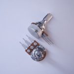
- a potentiometer. You can use any analog sensor you choose, however.
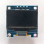
- an SSD1306 OLED breakout board
There are many breakout boards that use the SSD1306 OLED: Adafruit, Sparkfun , DFRobot, Crystalfontz, MakerFocus, Amazon, and many others. It typically comes in a 128×32 pixel version and a 128×64 pixel version. Solomon Systech makes other variations on this display as well, like the SSD1309 or the 1315. They come with different resolutions, different physical sizes, and different features.
Most of the SSD1206 displays have all blue pixels, but there are some models on the market have one section of yellow pixels and the rest blue. You can’t change the color of the pixels, so be aware of what you are buying and choose what you need. If you need a board with all blue pixels, don’t get the one with the yellow section.
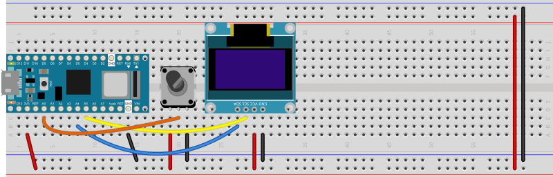
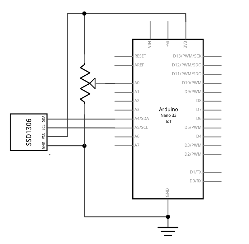
Connect the display’s voltage and ground pins to your voltage and ground buses, and the I2C clock (SCL) and I2C serial data (SDA) pins to your microcontroller’s corresponding I2C pins as shown in Figure 6-7. The schematic, Figure 6, is the same for both the Uno and the Nano. For the Arduino Uno or the Arduino Nano boards, the I2C pins are pins A4 (SDA) and A5(SCL). This is the same connection for almost any I2C device.
Connect the potentiometer’s two outside connections to power and ground, respectively. Connect the middle pin (the wiper) to the Arduino’s pin A0. You’ll use the potentiometer to generate something to display on the screen.
Once you’ve got the circuit wired as shown in Figures 6-7, you’re ready to program the microcontroller.
Program the Microcontroller
There are many libraries available for controlling the SSD1306 OLED screens. Adafruit’s SSD1306 library works well with all the SSD1306 displays, both the 128×64 and 128×32 models. Adafruit’s library is consistent with many of their other display libraries, and they make a lot of them. So it’s a good place to start. It doesn’t work with other SSD13xx models though. For example, Sparkfun makes a Micro OLED with the SSD1309, which has a 64×48 resolution. It requires a different library.
The u8g2 library by Oli Kraus, is intended as a universal monochrome display library for OLED, eInk, TFT, and other displays. It supports some SSD130x boards, but not all. It’s a pretty good library, but lacks some of the features of the Adafruit library. The examples included here use the Adafruit library. You’ll also need the Adafruit_GFX library which supports graphics across a number of small displays.
Import the Libraries
At the start of your sketch, import the libraries and set up a variable to hold the display driver instance like so:
#include <Wire.h>
#include <Adafruit_SSD1306.h>
#include <Adafruit_GFX.h>

const int SCREEN_WIDTH = 128; // OLED display width, in pixels
const int SCREEN_HEIGHT = 64; // OLED display height, in pixels

// initialize the display:
Adafruit_SSD1306 display(SCREEN_WIDTH, SCREEN_HEIGHT);
Initialize the Display
In the setup, you need to check that the display is working. If it fails, it’s a good idea to stop and notify the user. Since there’s no user interface in this basic sketch, you’ll use the Serial Monitor.
void setup() {
  // initialize serial and wait for serial monitor to open:
  Serial.begin(9600);
  if (!Serial) delay(3000);
  // first parameter of begin() sets voltage source.
  // SSD1306_SWITCHCAPVCC is for 3.3V
  // second parameter is I2C address, which is
  // 0x3C, or 3D for some 128x64 modules:
  if (!display.begin(SSD1306_SWITCHCAPVCC, 0x3C)) {
    Serial.println("Display setup failed");
    while (true);
  }
  Serial.println("Display is good to go");
}
Print to the Display
You can print to the display by giving it a text size and cursor position and then using .print() or .println(). The loop below reads analog input 0, then prints the time in seconds on the first line and the sensor reading on the second.
The function which actually updates the display is called .display(). All of the other functions update a buffer in the microcontroller’s memory. So you can make all the changes you want with commands like .print(), .setCursor(), .clearDisplay(), and so forth, but you will only see the changes when you call .display(). This is typical of many display libraries.
In the code below, you’ll clear the display, then set the size to twice the default, then move the cursor to the top left. Then you print the seconds since the sketch started, move the cursor down a line, and print the analog 0 sensor reading. Finally, you push it all to the display using .display():
void loop() {
  int sensorReading = analogRead(A0);
  // clear the display:
  display.clearDisplay();
  // set the text size to 2:
  display.setTextSize(2);
  // set the text color to white:
  display.setTextColor(SSD1306_WHITE);

  // move the cursor to 0,0:
  display.setCursor(0, 0);
  // print the seconds:
  display.print("secs:");
  display.print(millis() / 1000);

  // move the cursor down 20 pixels:
  display.setCursor(0, 20);
  // print a sensor reading:
  display.print("sensor:");
  display.print(sensorReading);
  // push everything out to the screen:
  display.display();
}
Here’s a link to the full sketch.
The SSD1306 is a monochrome display, but you still have to set the color to see anything display, because the library defaults to no colors. For a list of what SSD1306_WHITE and the other constants in the library mean, see this link.
Fonts
The default font of the library is not terribly attractive, and gets blocky when you increase the size. But you can add fonts. The Adafruit_GFX library includes many fonts compatible with lots of their display libraries. Search for this library in the library manager and include it to use the fonts. They have a good tutorial on using fonts as well. The short version is as follows. First, include the font you want to use with your library includes like so:
#include<Fonts/FreeSans9pt7b.h>
Next, in your setup() or whenever you want to switch fonts, use the .setFont() function like so:
display.setFont(&FreeSans9pt7b);
The text will now appear using your chosen font. Here’s a link to an example using one of the Adafruit_GFX fonts.
One of the nice things about using custom fonts is if you pick the right size for your screen, you don’t need to use .setTextSize(), so you can avoid pixelating your font. Note that custom fonts generally measure pixel height from the baseline. So, to position a 16-point font at the top of the screen, for example, position it with a few pixels at the top to spare: at (0, 20), not (0,0).
You can also use more custom fonts by generating them from this OLED display custom font generator. For “Library Version” choose “Adafruit GFX Font”. This will generate a custom header file that you include with your sketch. Make a new tab in the IDE, give the tab a name like font.h, and include it at the top of your code with the other library header files. The font name will be at the bottom of the header file. For example, if you generated the Dialog Font, Plain, 16 point, the font name would be Dialog_plain_16 and you’d include it just like the one above, like so:
display.setFont(&Dialog_plain_16);
The text will now appear using your custom font. Here’s a link to an example using a custom-generated font.
Graphics
There are many libraries for graphics on small displays. Typically these displays don’t have a fast refresh rate, so you can’t exactly create fast action games on them, but they can be good for simple graphic informational displays. Different display libraries will have slightingly different naming schemes for their graphics, but you can usually count on being able to draw points, lines, rectangles, circles, and sometimes rounded rects and triangles. You can generally also count on functions like drawRect() vs. fillRect() depending on whether you want a filled rectangle or not. All libraries will include methods for setting a color, clearing a screen, and filling the screen with a color. Most will also include commands for rotating the graphics display. Here’s the Adafruit_GFX library graphics primitives tutorial as an example.
Remember, all of your commands are only executed when you call .display().
Here’s a link to a graphic example that graphs the sensor reading. If you haven’t already included the Adafruit_GFX library, you will need to for this.
Displaying QR Codes
One way you can use the graphic capabilities of any small display is to show QR codes. QR codes can contain any string of text you want in a machine-readable form. Though we’re used to generating QR codes to supply web addresses (URLs), you can also send plain text strings, phone numbers, passcodes or other test-based information as well. On microcontroller-based devices, they can be a way to transfer identifying information like IP or MAC addresses, Bluetooth LE service UUIDs, or anything else your mobile phone or tablet might need to know about your microcontroller device in order to communicate with it.
QR codes can be generated from a text string and translated to a microcontroller display using Richard Moore’s qrcode library for Arduino and the graphics library for your particular display.
Like any library, you need to include the qrcode library at the top of your code like so:
#include <qrcode.h>
Determining QR Code Block Size
A QR code’s block size is the height and width of each of the blocks in the code. It depends size depends on the number of blocks per side. The length of the string you plan to display and a few other factors affect the block size. Here’s a table which lays out how the string length, error correction, and QR code version affect the the pixel dimensions of a QR code. Here’s a simpler version in the documentation for the qrcode library. A long string or higher levels of error correction can result in largee QR codes than you can fit on a small display. The library’s .size() function can give you the number of blocks in your QR code.
QR Codes need a “quiet zone” around the block in order to be readable to another device, so you can’t fill your display’s entire length or width with a QR code.
Here’s a good rule of thumb to get a block size that you can fit on your display:
- Set the QR version and the QR error level
- Start with an arbitrary offset. The larger your offset, the smaller the QR code can be.
- Subtract twice the offset width (also arbitrary) from the display’s smallest dimension (64px, in the case of the SSD1306)
- divide by the qrcode.size
Here’s a function to generate a QR code. It will take a String object, the QR code version you want to use, and the QR code error level you want, then it will generate a QRCode object, and display it on the display using the display library’s .fillRect() function:
void displayQrCode(String message) {
  // Create the QR code
  QRCode qrcode;
  int qrVersion = 3;
  int qrErrorLevel = ECC_MEDIUM;
  int offset = 2;
  int backgroundColor = SSD1306_BLACK;
  int foregroundColor = SSD1306_WHITE;

  // allocate QR code memory:
  byte qrcodeBytes[qrcode_getBufferSize(qrVersion)];
  // initialize the QR code text:
  qrcode_initText(&qrcode, qrcodeBytes, qrVersion, qrErrorLevel, message.c_str());
  // calculate the QR code block size:
  int blockSize = (display.height() - (offset * 2)) / qrcode.size;
  // fill the screen with the background color:
  display.fillScreen(backgroundColor);

  // read the bytes of the QR code and set the blocks light or dark, accordingly:
  // vertical loop:
  for (byte y = 0; y < qrcode.size; y++) {
    // horizontal loop:
    for (byte x = 0; x < qrcode.size; x++) {
      // calculate the block's X and Y positions:
      int blockX = (x * blockSize) + offset;
      int blockY = (y * blockSize) + offset;
      // read the block value from the QRcode:
      int blockValue = qrcode_getModule(&qrcode, x, y);
      // set the default block color:
      int blockColor = backgroundColor;
      // if the block value is 1, set color to foreground color instead:
      if (blockValue == 1) {
        blockColor = foregroundColor;
      }
      // display the block on the screen:
      display.fillRect(blockX, blockY, blockSize, blockSize, blockColor);
    }
  }
  // refresh the display here, after the nested loops:
  display.display();
  // print the message:
  Serial.println(message);
}
Here’s a link to a full sketch to generate QR codes on an SSD1306 display. Upload it to your Nano, then open the serial monitor and enter a string to display. Then scan the QR Code with your phone’s QR scanning app. You should be able to read short strings of text, up to 50 or so characters. You can also send URLs, phone numbers, or anything else your phone’s QR code reader can interpret.
The shorter the string, the easier it is for your QR code scanner to read it. This is why many URLs you see on QR codes in public use URL shorteners.
Conclusion
Even though the SSD1306 is a small, low resolution monochrome display, it packs a lot of potential for the price. Adding an informational display can improve many devices, and by adding a QR code, you have the possibility to add many more features through the web, Bluetooth, and more. For more on microcntroller displays, see this repository.