Introduction
In this lab, you’ll build an alternative computer mouse using any of the USB-native boards (the MKR series, the Due, the Leonardo, the Micro, and the Feather M0 series all fit this requirement). You’ll also learn some techniques for determining when a user takes a physical action. In the Digital Lab and Analog Lab, you learned how to read the input from a digital or analog input, but you didn’t learn anything about how to interpret the stream of data as an event. There are a few everyday physical interactions that are fairly easy to pick out from a stream of data. You’ll see a few of them in this lab.
Keyboard and Mouse are examples of the USB Human Interface Device (HID) profile. There is another library, the HID-project library, which extends Keyboard and Mouse to do things like using the consumer keys (alternate functions of the F-keys), power key, and so forth.
This lab should should work on SAMD Arduino boards (MKR series, Nano 33 IoT), as well as the Leonardo, Due, and other USB-native boards.
What You’ll Need to Know
To get the most out of this lab, you should be familiar with the following concepts. You can check how to do so in the links below:
Things You’ll Need
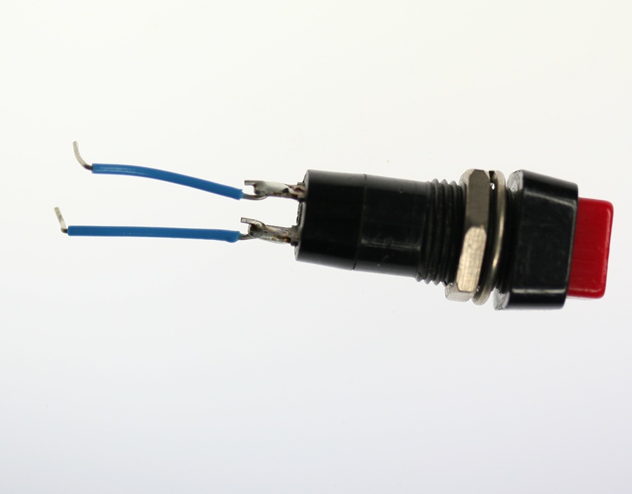
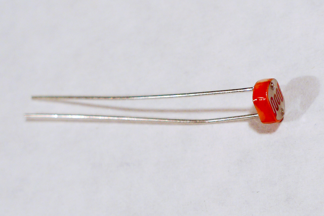
Figures 1-6 show the parts you’ll need for this exercise. Click on any image for a larger view.


About mouse control
NOTE: The sketches contained in this lab will cause the Arduino Leonardo to take control of your mouse. Make sure they’re working properly before you add the mouse commands. The example doesn’t introduce the mouse commands until the end of the lab. Instead, messages are printed to the serial monitor to tell you what should happen. When you’ve run this and seen the serial messages occurring when you think they should, then you can add the mouse commands safely.
The sketches here will work on an Uno until you add the mouse commands. So you can test this on an Uno or any board that’s not USB-native simply by commenting out the Mouse.h include at the top of the code below, and any line that says Mouse.begin() or Mouse.move().
Note on Mouse, Keyboard, and Serial Ports
The Mouse and Keyboard libraries on the SAMD boards (MKRZero, MKR1xxx, Nano 33IoT) have an unusual behavior: using them changes the serial port enumeration. When you include the Keyboard library in a sketch, your board’s serial port number will change. For example, on MacOS, if the port number is /dev/cu.usbmodem14101, then adding the Keyboard library will change it to /dev/cu.usbmodem14102. Removing the Keyboard library will change it back to /dev/cu.usbmodem14101. Similarly, if you double-tap the reset button to put the board in bootloader mode, the serial port will re-enumerate to its original number.
Windows and HID Devices
You may have trouble getting these sketches to work on Windows. On Windows, the default Arduino drivers must be uninstalled so the system can recognize the Arduino as both serial device and HID device. Read this issue and follow the instructions there.
Recovering From a Runaway HID (Mouse or Keyboard) Sketch
Programs which control your keyboard and mouse can make development difficult or impossible if you make a mistake in your code. If you create a mouse or keyboard example that doesn’t do what you want it to, and you need to reprogram your microcontroller to stop the program, do this:
Open a new blank sketch.
This sketch is your recovery:
void setup() {

}
void loop() {

}
Programming the board with this blank sketch removes your mistaken sketch and gives you control again. To do this, however, you need the current sketch to stop running. So:
Put the microcontroller in bootloader mode and upload the blank sketch
On the SAMD boards, you can do this by double-tapping the reset button. The on-board LED will begin glowing, and the bootloader will start so that you get a serial port enumeration, but the sketch won’t run. On the Leonardo and other 32U4-based boards, hold the reset down until you’ve given the upload command. The 32U4 bootloader will take a few seconds before it starts the sketch, so the uploader can take command and load your blank sketch.
Once you’ve got the blank sketch on the board, review the logic of your mistaken Keyboard or Mouse sketch and find the problem before uploading again.
Prepare the breadboard
Connect power and ground on the breadboard to power and ground from the microcontroller. On the Arduino module, use the 5V and any of the ground connections.
In Figure 7 you see an Arduino Leonardo on the left connected to a solderless breadboard, right. The Leonardo’s 5V output hole is connected to the red column of holes on the far left side of the breadboard. The Leonardo’s ground hole is connected to the blue column on the left of the board. The red and blue columns on the left of the breadboard are connected to the red and blue columns on the right side of the breadboard with red and black wires, respectively. These columns on the side of a breadboard are commonly called the buses. The red line is the voltage bus, and the black or blue line is the ground bus. See Figure 8 for the breadboard view with Arduino Nano.
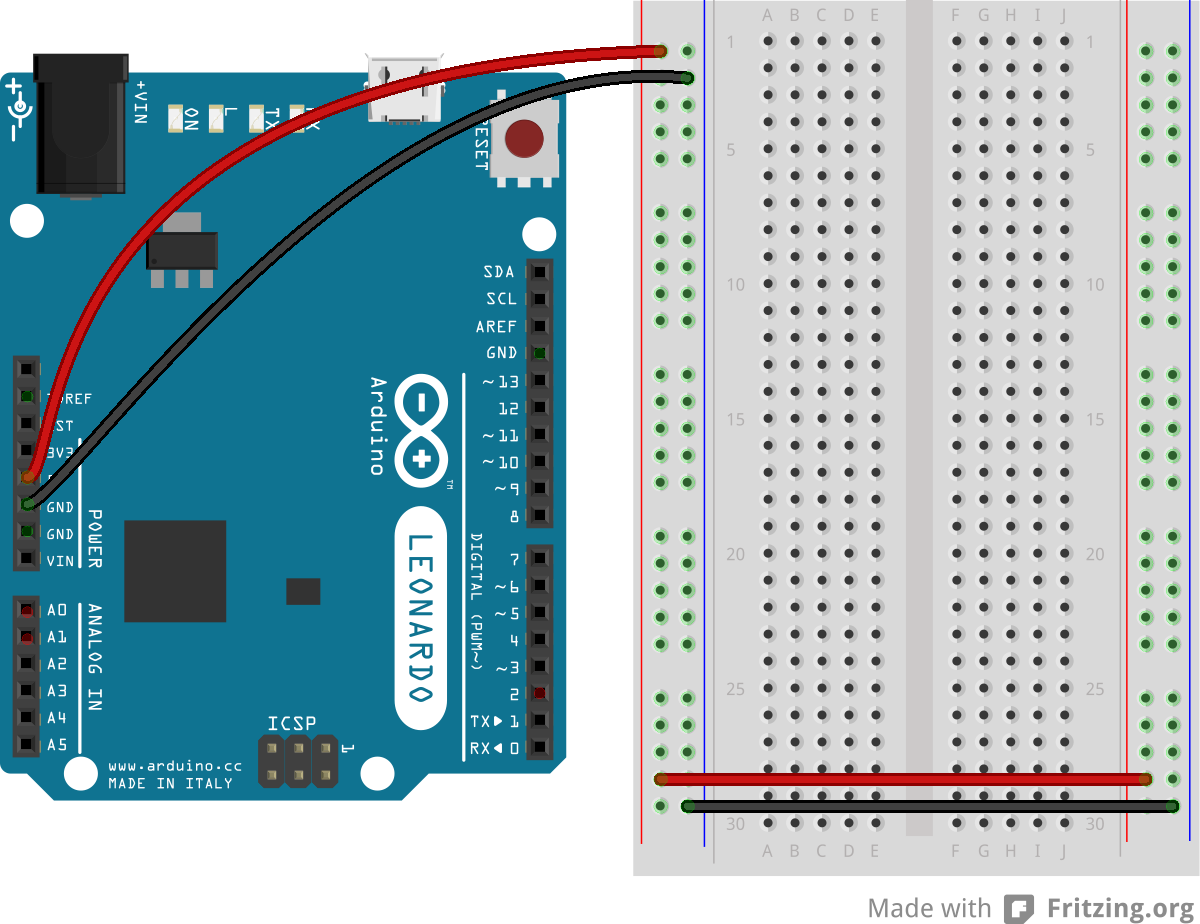

Figure 8. Breadboard view of an Arduino Nano connected to a breadboard. The +3.3 volts and ground pins of the Arduino are connected by red and black wires, respectively, to the left side rows of the breadboard. +3.3 volts is connected to the left outer side row (the voltage bus) and ground is connected to the left inner side row (the ground bus). The side rows on the left are connected to the side rows on the right using red and black wires, respectively, creating a voltage bus and a ground bus on both sides of the board.
Made with Fritzing
Add a pushbutton
Attach a pushbutton to digital pin 2. Connect one side of the pushbutton to 5 volts, and the other side of the pushbutton to a 10-kilohm resistor. Connect the other end of the resistor to ground. Connect the junction where the pushbutton and the resistor meet to digital pin 2. (For more on this digital input circuit,see the Digital Input Lab)
In Figure 9 and Figure 10 you see a schematic drawing and a breadboard drawing of an Arduino Leonardo connected to a pushbutton. Figure 11 shows the Nano 33 IoT version. The pushbutton straddles the center divide of the breadboard in rows 20 through 22. A red wire connects row 20 on the right center side to the right side voltage bus. A 10-kilohm resistor connects row 22 on the right center side to row 26 on the same side. A black wire connects from row 26 to the ground bus on the right side. A blue wire connects row 22 on the left center side of the board to digital pin 2. See Figure 11 for the breadboard view with Arduino Nano.
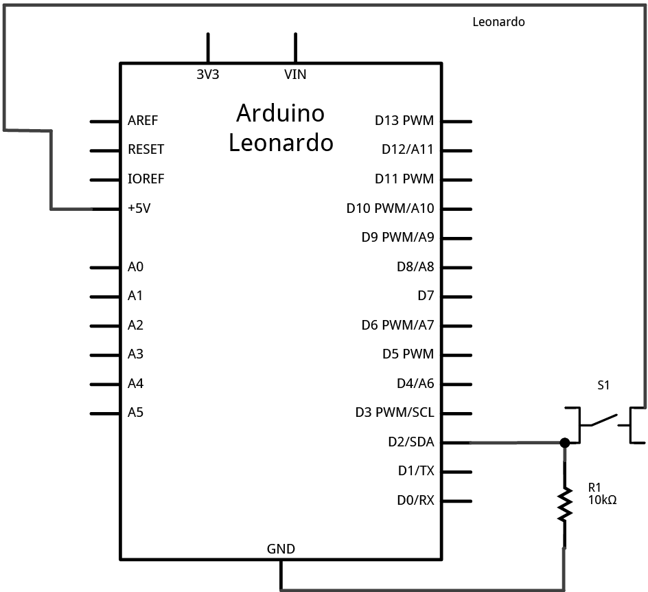
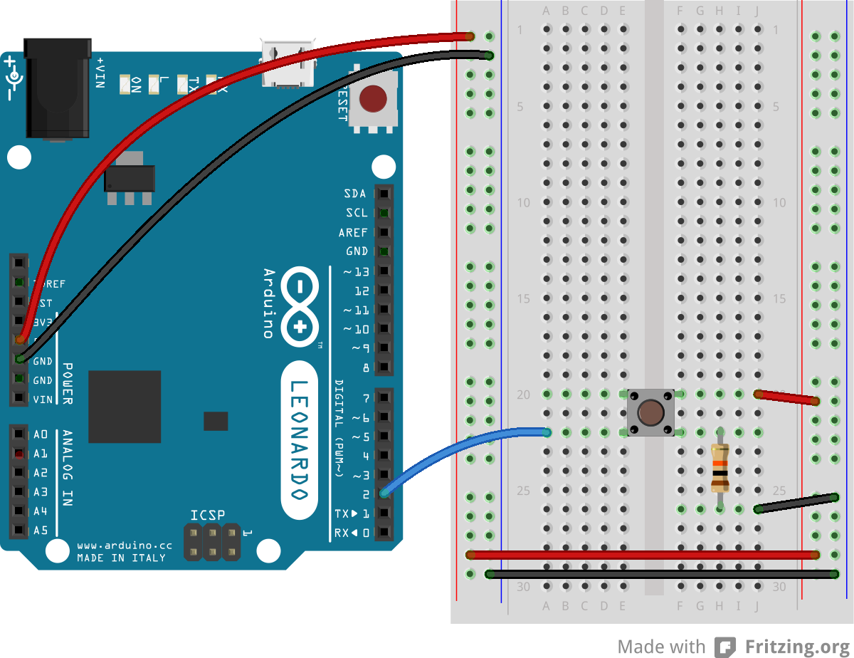
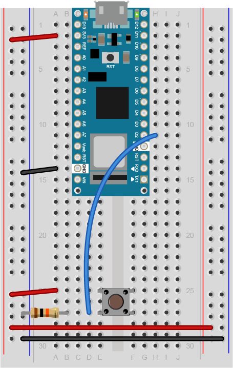
Figure 11. Breadboard view of an Arduino Nano connected to a pushbutton. The +3.3 volts and ground pins of the Arduino are connected by red and black wires, respectively, to the left side rows of the breadboard. +3.3 volts is connected to the left outer side row (the voltage bus) and ground is connected to the left inner side row (the ground bus). The side rows on the left are connected to the side rows on the right using red and black wires, respectively, creating a voltage bus and a ground bus on both sides of the board. The pushbutton is mounted across the middle divide of the solderless breadboard. A 10-kilohm resistor connects from the same row as pushbutton’s bottom left pin to the ground bus on the breadboard. There is a wire connecting to digital pin 2 from the same row that connects the resistor and the pushbutton. The top left pin of the pushbutton is connected to +3.3V.
Add two analog inputs
Attach a photoresistor to 5 volts. Attach a 10-kilohm resistor from the other side of the photoresistor to ground. Attach the junction where the photocell and the resistor meet to analog input 0. Do the same for analog input 1. You can use any variable resistor in place of the photoresistors: flex sensors, force-sensing resistors, or whatever feels good to you.
In Figure 12 and Figure 13 you see a schematic drawing and a breadboard drawing of an Arduino Leonardo connected to a pushbutton and two voltage divider inputs. The pushbutton is connected as described in the previous breadboard drawing. Two photoresistors are mounted in the right center section of the breadboard. The first is connected to rows 2 and 5. The second is connected to rows 11 and 14. Rows 2 and 11 are also connected to the right side voltage bus through red wires. Two 10-kilohm resistors are also mounted in the right center section. The first is connected to rows 5 and 9, and the second is connected to rows 14 and 18. Rows 9 and 18 are connected to the right side ground bus. The four resistors thus form two voltage dividers. A blue wire extends from the middle of each divider to the analog pins. The first goes from row 5 to pin A0, and the second from row 14 to pin A1. See Figure 14 for the breadboard view with Arduino Nano.
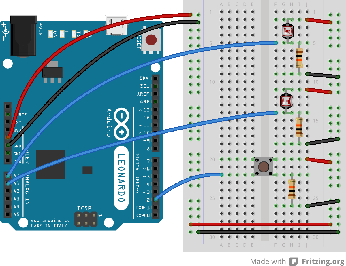
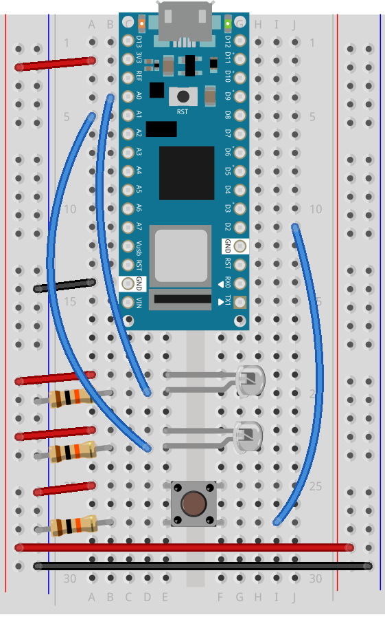
Figure 14. Breadboard drawing of an Arduino Nano connected to a pushbutton and two phototransistors. The pushbutton connects remain the same as described in the previous diagram. The short legs of the phototransistors connect to the voltage bus. The longer legs of each phototransistor each connect a 10-kilohm resistor to the ground bus and a blue wire to the analog pins of the Arduino Nano, the first goes to pin A0, and the second to pin A1.
Program the module to read the pushbutton
In the Digital Lab you learned how to read a pushbutton using the digitalRead() command. To tell when a pushbutton is pushed, you need to determine when the button’s state changes from off to on. With the pushbutton wired as you have it here, its state will change from 0 to 1. In order to know that, you need to know not only what the current state of the button is, but you also need to remember the state of the button the previous time you read it.
To do this, set up a global variable to store the button’s previous state. Initialize the button in your program’s setup() function using the pinMode() command. Then, in the loop() function, write a block of code that reads the button and compares its state to the previous state variable. To do this, you need to read the button, check the current button state against the last state, then save the current state of the button in a variable for the next time through the loop like so:
int lastButtonState = LOW;        // state of the button last time you checked

void setup() {
  // make pin 2 an input:
  pinMode(2, INPUT);
}

void loop() {
  // read the pushbutton:
  int buttonState = digitalRead(2);

  // check if the current button state is different than the last state:
  if (buttonState != lastButtonState) {
     // do stuff if it is different here
  }

  // save button state for next comparison:
  lastButtonState = buttonState;
}
If buttonState is not equal to lastButtonState, then the button has changed. Then you want to check if the current state is HIGH. If it is, then you know the button has changed from low to high. That means your user pressed it. Print out a message to that effect.
int lastButtonState = LOW;        // state of the button last time you checked

void setup() {
  // initialize serial communication:
  Serial.begin(9600);
  // make pin 2 an input:
  pinMode(2, INPUT);
}

void loop() {
  // read the pushbutton:
  int buttonState = digitalRead(2);

  // if it's changed and it's high, toggle the mouse state:
  if (buttonState != lastButtonState) {
    if (buttonState == HIGH) {
      Serial.println("Button was just pressed.");
    }
  }
  // save button state for next comparison:
  lastButtonState = buttonState;
}
Your code should only print out a message when the button changes state. For every button press, you should get one line of code. If you’re getting multiple lines of code for every button press, you did it wrong.
Set up a variable to track whether or not you’re controlling the mouse
This sketch is going to take control of your computer’s mouse when you finish it. If you get it wrong, that can cause real problems, because you won’t be able to control your computer until you unplug the Leonardo. So you want to make sure you’ve got a way to turn off control of the mouse. You’ll use this pushbutton to turn on or off the Leonardo’s control of the mouse.
To do this, set up a global variable called mouseIsActive. Initialize it as false. When the button is pressed, change this variable from false to true, or true to false, depending on its state. This should be a boolean variable. This variable doesn’t actually change anything yet, but later on, you’ll decide whether to issue mouse movement commands depending on whether it’s true or false.
// Global variables:
int lastButtonState = LOW;            // state of the button last time you checked
boolean mouseIsActive = false;    // whether or not the Arduino is controlling the mouse

void setup() {
  // initialize serial communication:
  Serial.begin(9600);
  // make pin 2 an input:
  pinMode(2, INPUT);
}

void loop() {
  // read the pushbutton:
  int buttonState = digitalRead(2);

  // if it's changed and it's high, toggle the mouse state:
  if (buttonState != lastButtonState) {
    if (buttonState == HIGH) {
      // if mouseIsActive is true, make it false;
      // if it's false, make it true:
      mouseIsActive = !mouseIsActive;
      Serial.print("Mouse control state: ");
      Serial.println(mouseIsActive);
    }
  }
  // save button state for next comparison:
  lastButtonState = buttonState;
}
Read the sensors and decide on a threshold for action
The photoresistors in the circuit above will be used to detect whether the user wants to move left or right. Set them up close to each other in the same light. When the user waves her hand over the top one in the image above, you’ll move the mouse cursor to the left, and when she waves her hand over the bottom one, you’ll move it to the right. Nothing should happen if she doesn’t have her hands over the sensors, or if she has her hands over both sensors.
Since they’re in the same light, they should read identically. So to detect hands, you want to look for a significant difference between the sensors. When there’s a significant difference between them, you’ll make a move. When the top sensor is higher, you’ll move to the left. When the one on the bottom is higher, you’ll move to the right.
Add code to the main loop to read the sensors into two variables, sensor1 and sensor2, with a one-millisecond delay between readings. Then print the results.
// Global variables:
int lastButtonState = LOW;            // state of the button last time you checked
boolean mouseIsActive = false;    // whether or not the Arduino is controlling the mouse

void setup() {
  // initialize serial communication:
  Serial.begin(9600);
  // make pin 2 an input:
  pinMode(2, INPUT);
}

void loop() {
  // read the pushbutton:
  int buttonState = digitalRead(2);

  // if it's changed and it's high, toggle the mouse state:
  if (buttonState != lastButtonState) {
    if (buttonState == HIGH) {
      // if mouseIsActive is true, make it false;
      // if it's false, make it true:
      mouseIsActive = !mouseIsActive;
      Serial.print("Mouse control state: ");
      Serial.println(mouseIsActive);
    }
  }
  // save button state for next comparison:
  lastButtonState = buttonState;

// read the analog sensors:
  int sensor1 = analogRead(A0);
  delay(1);
  int sensor2 = analogRead(A1);

  // print their values:
  Serial.print(sensor1);
  Serial.print("  ");
  Serial.println(sensor2);
}
Right after this in the main loop, add code to compare the two values. If there is more than 100 points difference, print L or R, depending on which sensor is higher (L for the top sensor, R for the bottom):
// if there's a significant difference to the right:
  if (sensor1 > sensor2 + 100) {
    Serial.println("L");
  }

  // if there's a significant difference to the left:
  else if (sensor2 > sensor1 + 100) {
    Serial.println("R");
  }
When you run this sketch now, you should see an L or R every time there’s a significant difference (> 100) between the sensors. When you push the button, you should get a report of the mouse control state, 1 for true and 0 for false. Run it and open the serial monitor to see that happen.
Add mouse control
Now it’s time to add mouse control commands.
NOTE: The sketches contained in this lab will cause the Arduino Leonardo to take control of your mouse. Make sure they’re working properly before you add these commands. The example doesn’t introduce the mouse commands until the end of the lab. Instead, messages are printed to the serial monitor to tell you what should happen. When you’ve run this and seen the serial messages occurring when you think they should, then you can add the mouse commands safely.
The sketches here will work on an Uno until you add the mouse commands. So you can test this on an Uno simply by commenting out any line that says Mouse.begin() or Mouse.move().
If your sketch causes your mouse to misbehave, upload a blank sketch (the default when you choose File -> New) to your Leonardo and you can start again from the beginning.
The Mouse.begin() command is called in the setup. It initializes mouse control from your Leonardo.
The Mouse.move() command has three parameters: the horizontal movement, the vertical movement, and the scroll wheel movement. All movements are relative, so Mouse.move(1,0,0); moves one pixel to the right; Mouse.move(-1,0,0); moves one pixel to the left; Mouse.move(0,1,0); moves one pixel down; and Mouse.move(0,-1,0); moves one pixel up.
At the top of your code, include the Mouse library. Then Modify the setup by adding the command Mouse.begin(). Then, in the loop where you print L or R, add Mouse.move commands to move left or right, as needed.
#include "Mouse.h"                // include the mouse library
// Global variables:
int lastButtonState = LOW;        // state of the button last time you checked
boolean mouseIsActive = false;    // whether or not the Arduino is controlling the mouse

void setup() {
  // initialize mouse control:
  Mouse.begin();
  // initialize serial communication:
  Serial.begin(9600);
  // make pin 2 an input:
  pinMode(2, INPUT);
}

void loop() {
  // read the pushbutton:
  int buttonState = digitalRead(2);

  // if it's changed and it's high, toggle the mouse state:
  if (buttonState != lastButtonState) {
    if (buttonState == HIGH) {
      // if mouseIsActive is true, make it false;
      // if it's false, make it true:
      mouseIsActive = !mouseIsActive;
    }
  }
  // save button state for next comparison:
  lastButtonState = buttonState;

  // read the analog sensors:
  int sensor1 = analogRead(A0);
  delay(1);
  int sensor2 = analogRead(A1);

  // print their values. Remove this when you have things working:
  Serial.print(sensor1);
  Serial.print("  ");
  Serial.println(sensor2);

  // if there's a significant difference to the right:
  if (sensor1 > sensor2 + 100){
    //  Serial.println("L");
    if (mouseIsActive == true) {
      Mouse.move(-1, 0, 0);
    }
  }

  // if there's a significant difference to the left:
  else if (sensor2 > sensor1 + 100) {
    // Serial.println("R");
    if (mouseIsActive == true) {
      Mouse.move(1, 0, 0);
    }
  }
}
That’s the whole sketch. When you run this, press the button to enable or disable mouse control, then put your hands over the sensors to move the mouse left or right.
The full sketch for this can be found on the phys comp github repository, called MouseMoveSimple
Once you’ve got that working, move on to the Mouse Control With Pushbuttons lab.