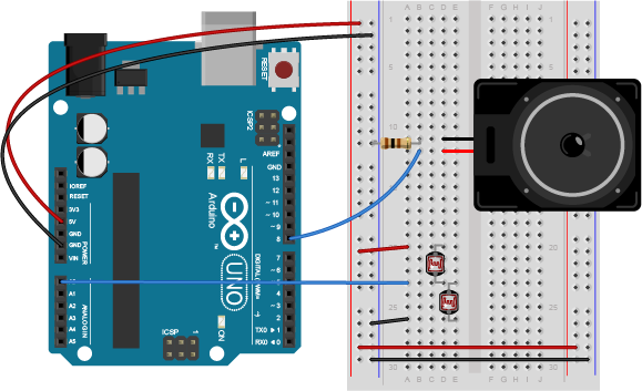
Breadboard view of an Arduino connected to two force-sensing resistors and a speaker. The Arduino’s voltage out and ground pins are connected to the voltage and ground buses of the breadboard as usual. The FSRs are mounted in the left center section of the breadboard. One leg of the first FSR is connected to 5 volts. The other leg is connected simultaneously to the first leg of the second FSR and the Arduino’s analog input pin A0. The second leg of the second FSR is connected to ground. The red positive wire of the speaker is connected to digital pin 8 of the Arduino. The black ground wire of the speaker is connected to one leg of a 100 ohm resistor. The other leg of the resistor connects to ground.