In this tutorial you’ll learn the basics of soldering for electronics.
Introduction
If you’re going to do any electronics work, you’re going to have to do some soldering, or have someone help you do it. Many people fear it before they’ve done it, but it’s really pretty simple to do. This exercise will show you how to solder a DC Power connector to a set of wires for a breadboard.
In order to get the most out of this tutorial, you should have a basic understanding of electrical circuits, so you understand why you’re soldering, and you should know what a solderless breadboard is.
You might also find this video on soldering by Andy Sigler and this video on desoldering helpful.
Soldering is a process in which you use a metal alloy with a low melting point to fuse together two other pieces of metal. It’s used in electronics all the time, because it ensures a mechanically solid connection between two materials that’s also electrically conductive. To do this, you heat the alloy, called solder, until it melts, and let it run across the two metal pieces you’re attempting to join.
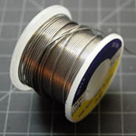
There are many different ways to solder, but the most common for hobbyists uses a handheld soldering iron and a reel of solder wire. That’s the process that’s demonstrated here.
Things You’ll Need
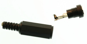

In the steps that follow, you’ll connect jumper wires to a power connector. When you’re prototyping a circuit, you need all of your parts to have connections that can fit firmly in a solderless breadboard. Many electronic components and connectors don’t have such connections, so you need to solder them on. The DC power jack shown in this exercise is one such connector. It comes with no wires, just connections onto which you’re expected to solder your own wires. You’ll solder wires onto it, and then you’ll solder a pair of stiff header pins onto the ends of the wires.
Preparing the parts
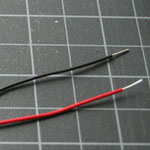
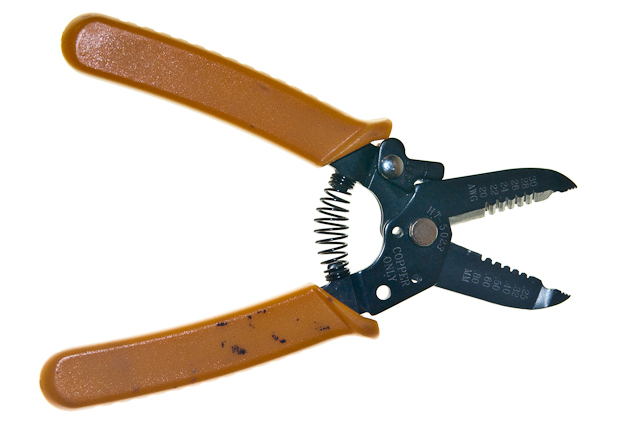
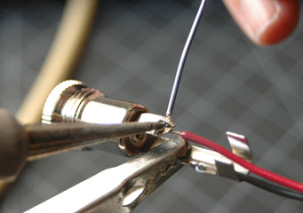
Cut a red and a black wire about four inches (10cm) in length. Strip the ends back about 1/4 of an inch (1/2 cm). Bend a hook on one end of each wire. Unscrew the power jack. As shown in Figure 9, connect the red wire to the hole in the the center tab of the power, and the black to the hole in the outside tab. Use pliers to crimp the hooked wires to their connections on the jack. If the connections aren’t soldered, you’ll get an inconsistent connection at best, and a short circuit at worst.
Related video: Wiring a power supply using a DC power jack
Heating the Soldering Iron (and the connections)
Heat up your soldering iron. It doesn’t need to be cranked to its maximum heat. For most small jobs like this, 600-700 degrees Fahrenheit (315-370 C) will work just fine. You really only need the iron hot enough to heat the metal connections so that they’ll melt the solder.
The best solder joints are those where the two metal connections to be joined are heated up together, and the solder is then melted by the heat of the connections. That way, all three metals cool down together. As they cool, they contract. You want them to contract together, so there is no cracking of the joint between them.
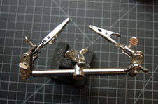
Make sure the two pieces of metal are touching each other firmly. Use a helping hand or a clamp to hold them in place. When they’re solidly touching, and held firmly by your clamp or helping hands, touch the iron to the joint between the wire and the metal to heat the joint (see Figure 10). Then touch the solder to the joint (NOT to the iron) until it melts. This should make a clean solder with a small blob of solder.
You may find that it takes longer to heat the connection in order for the solder to melt. The larger a connector is, the more time it takes to heat. This is because the metal of the connector is conducting the heat away from the joint. If your connector is too big, you may need to use a mechanical joint, as opposed to a solder joint. The DC power jacks shown in this tutorial will solder just fine, however.
As the solder cools down, its surface will go from shiny to a more matte surface. When it cools down, test the joint by wiggling it to make sure it’s firm.
Repeat the process with the other wire and the other part of the connector.
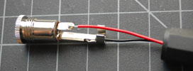
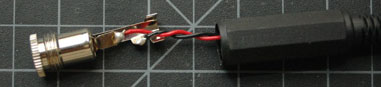
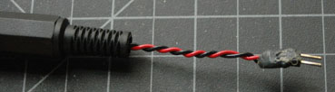
Twist the wires together and thread them through the sleeve of the jack.
The result should look like this in Figure 11:
Soldering the Header Pins
The two wires are now properly separated inside the connector, but the other ends can move freely. Even though these two ends can fit firmly in a breadboard, it can be dangerous to leave them loose. They might touch each other while you have the connector plugged in, causing a short circuit.
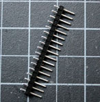
Header pins(Figure 12) are a great way to maintain the spacing between wires that you need to fit into a breadboard. If you solder two of them to the ends of your wires, with the metal spacer still on them, they’ll keep your wire leads safely apart.
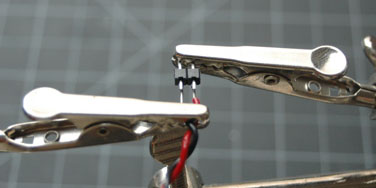
Trim the ends of the wires to the same length, and strip them back to about 1/8th of an inch. Break off two header pins and hold them in one clip of a helping hands device. Clip the wires in the other clip, and align them with the header pins like so in Figure 13:
Solder the wires to the headers. Move quickly, as the plastic spacer between the headers can melt (that’s another reason not to heat your iron too hot). When you’re done soldering, you should have two separate blobs like this in Figure 14:
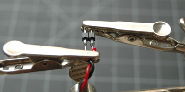
If you can’t see space between the two solder joints, de-solder them and do it again. You need to be sure there’s no connection between these wires that can cause a short circuit, and the best way to do that is to leave space.
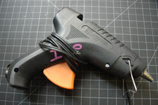
Take a hot glue gun and surround the bare connections to insulate them and provide some strain relief. When you’re done, you should have a connection like this in Figure 15:
Make sure you can tell which pin is connected to the red wire and which is connected to the black.
Testing
Before you connect it to power, take a meter and check the connections for continuity. The center pin should be connected to the red wire, and the outer rim should be connected to black. When that’s good, you’re ready to use it.
What Else Can I Solder?
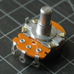
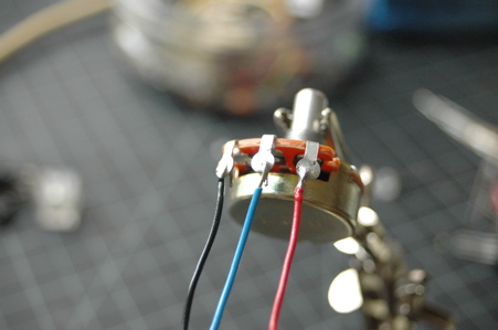
Any time you have loose mechanical connections, you should solder them if you can. For example, many common potentiometers have ring contacts(Figure 16). If you loop the wires around the rings as shown in Figure 17, you get inconsistent readings from your potentiometer. Solder the leads if they are loose.
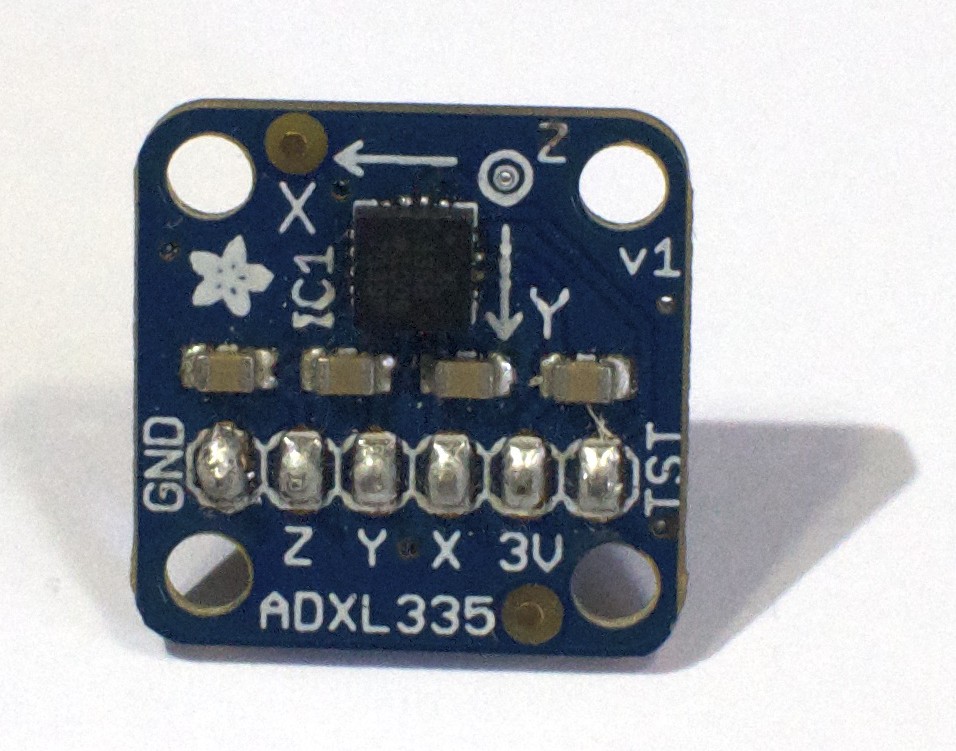
Many breadboard-friendly printed circuit boards come without headers soldered on. One of the most common mistakes beginners make with these boards is to push them into a breadboard using headers, but with no solder. This will also give inconsistent readings. Figure 18 shows an ADXL335 accelerometer module pins are properly soldered.
When in doubt, if you have loose connections, solder them!
For more on soldering, check out Adafruit’s soldering tutorial.