Lab: Switches and Pushbuttons

Introduction

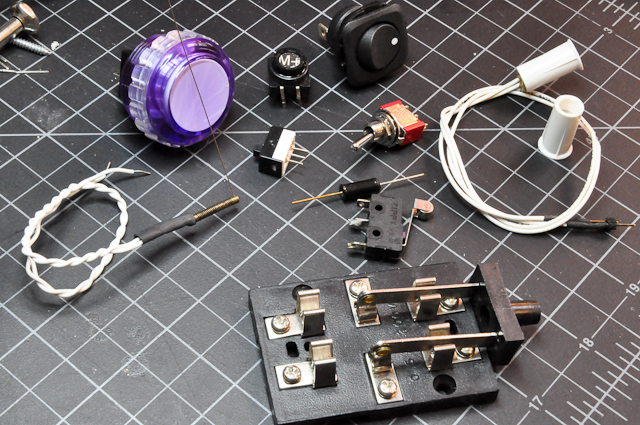
In this lab you will learn about different types of switches and their terminology. You’ll use switches and pushbuttons frequently in physical computing projects, as shown in Figure 1, and it’s helpful to be aware of the terminology used in describing them when shopping for them or trying to understand tutorials that use them.

An assortment of switches and pushbuttons. This image includes an arcade-style pushbutton; an old typewriter key; a round toggle switch; a small; rocker switch; a whisker switch, which is a thin wire attached to a spring wrapped around a metal post; a magnet switch, and a magnet that closes the switch when you bring it close; a tilt switch; a two-way knife switch.
Figure 1. Switches and pushbuttons. There are countless types of switches and pushbuttons for every purpose.

Switch Terminology

As shown in Figure 2, there are two common types of digital inputs: switches and pushbuttons. A switch is a mechanism that brings two pieces of metal together using some form of lever action. Think of everyday household light switches.  A pushbutton brings two pieces of metal together when you push down on it. Think of elevator buttons.

Drawing of a switch, left, and a pushbutton, right. The switch has two lines separated by a gap, with a hinged third line almost connecting them, indicating that it is the switch between the two contacts. The pushbutton has two lines separated by a gap and a third line parallel to them, indicating that, it would close the connection between the first two lines when pressed against them.
Figure 2. Schematic drawing of a switch and a pushbutton

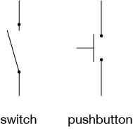
Switches and pushbuttons can be normally open, meaning that when the switch is in its normal position (not being touched by a person) the contacts are not touching. Normally closed means that when the switch or pushbutton is in its normal position, the contacts are touching, or closed.

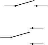
As shown in Figure 3, a single switch can control more than one set of contacts. A Single throw switch has only two contacts. The switch is open or closed. Dual Throw switches have three contacts, and switching the switch moves a center contact from one outer contact to  the other outer contact.

Drawing of two switch types. The top drawing has two lines separated by a gap, with a hinged third line almost connecting them, indicating that it is the switch between the two contacts. The bottom drawing has one line on the left, and two parallel lines on the right. A hinged fourth line almost connects the left line and the top right line, and indicates that it can be switched to connect the left line to the bottom right line instead.
Figure 3. Single throw switch, top, and dual throw switch, bottom.

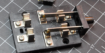
Switches can have multiple poles as well. A Single pole switch has only one set of contacts that it closes or opens when it moves. Dual Pole switches, as shown in Figure 4,  have two sets of contacts being controlled by the same mechanism. With a dual pole switch, you can switch two separate circuits with the same mechanism. In a dual pole switch, the mechanism connecting the contacts is an insulator, so that the poles don’t connect. The knife switch in the image below is a dual pole, dual throw switch.

Photo of a dual-pole, dual-throw switch. The switch has a metal lever with two legs connected by a crossbar mounted at its center. On either side of the crossbar are two sets of metal contacts. When the lever is pushed to one side or the other, it will close the connection between the two metal contacts on the side toward which it is pushed. This kind of switch is sometimes called a knife switch.
Figure 4. Dual-pole, dual-throw switch.

Related video: Switches

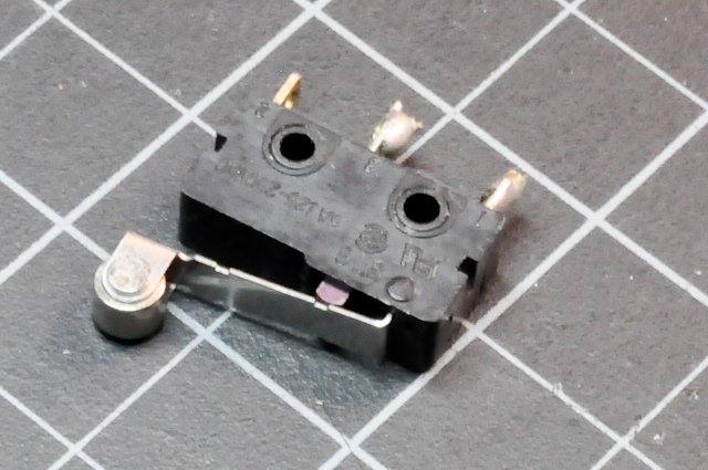
Pushbuttons(Figure 5) or momentary switches stay closed only as long as you hold them closed. Roller switches(Figure 6) are pushbuttons with a lever and a roller attached. They’re useful when you need something to push against the switch gently to close it.

Photo of a small round button, approximately 0.5 in (2-3cm) in diameter. The button has two legs on either side. Pushing the button closes the connection between the two legs on each side.
Figure 5. A pushbutton
Photo of a rocker switch. A rectangular component approx. 1 in (2-3cm) wide by 0.25 in (0.5cm) thick. A lever is mounted on one side, and three metal contacts on the other. Under the lever is a small plastic protrusion that is pushed down when the lever is pressed.
Figure 6. A roller switch. Even though this is commonly called a switch, this is really a pushbutton. The small black protrusion under the lever is pressed down by the lever arm.

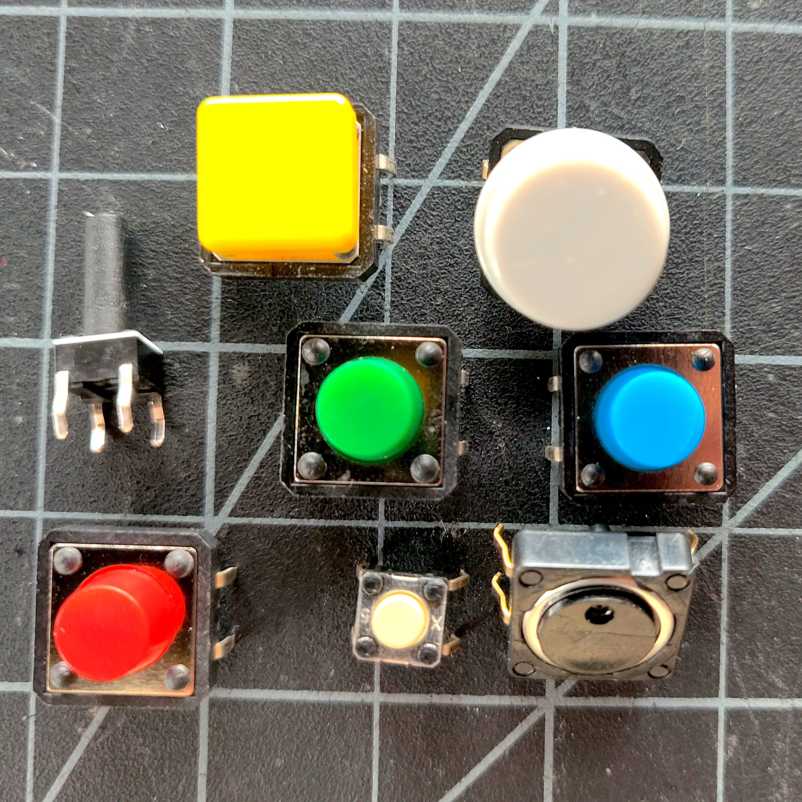
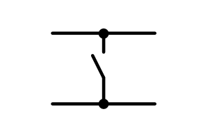
Tactile Switches are pushbuttons that have a tactile click to them (Figure 7). They are usually designed to be soldered to a circuit board, and they fit into a breadboard nicely as well. They are perhaps the most common switches you’ll use in physical computing. You can get them in a variety of colors and sizes.  They generally have four pins, arranged in a rectangle. If you hold the switch so that the wide side of the rectangle of pins is horizontal, then the top two pins are generally connected to each other, and the bottom two are connected to each other. The switch is between the two wide sides. The schematic in Figure 8 shows how they are wired.

Photo of a variety of different tactile switches.
Figure 7. A variety of different tactile switches. These all have different sizes and cap shapes, but they all have the same functionality and feel. Some tactile switches, like the one at the top left, have extra long caps.
Schematic of a typical tactile switch
Figure 8. Schematic of a typical tactile switch. The two top pins are connected to one side of the switching mechanism inside, and the two bottom pins are connected to the other side of the mechanism.

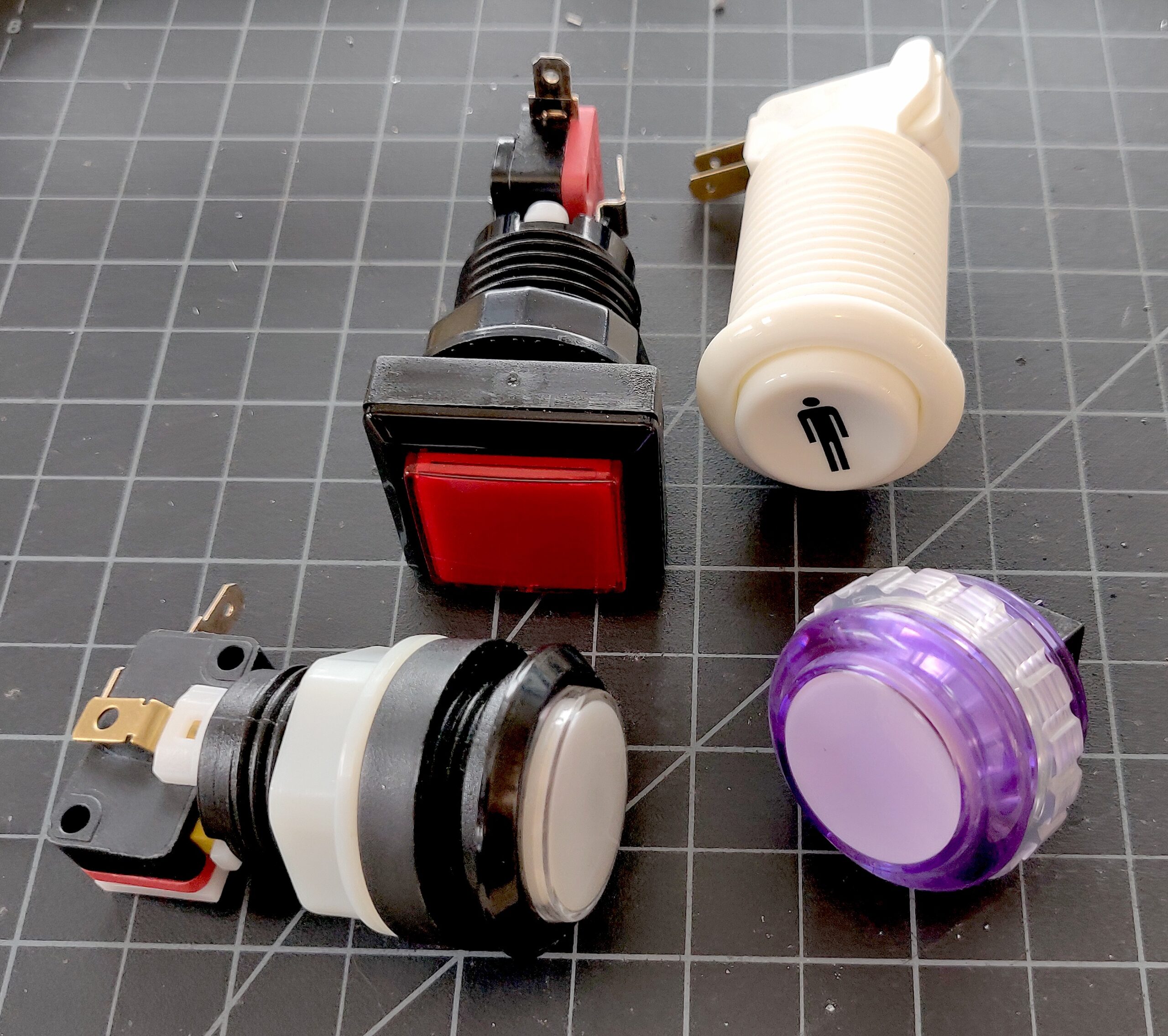
Arcade buttons (Figure 9) are popular game consoles because they are big and robust. They often have a built-in LED that you can control independently of the switch. In this way they are similar to other illuminated switches and pushbuttons.

Photo of several arcade buttons
Figure 9. Arcade buttons come in many different sizes and shapes. They are designed to be panel-mounted. Many are illuminated with an internal LED as well.

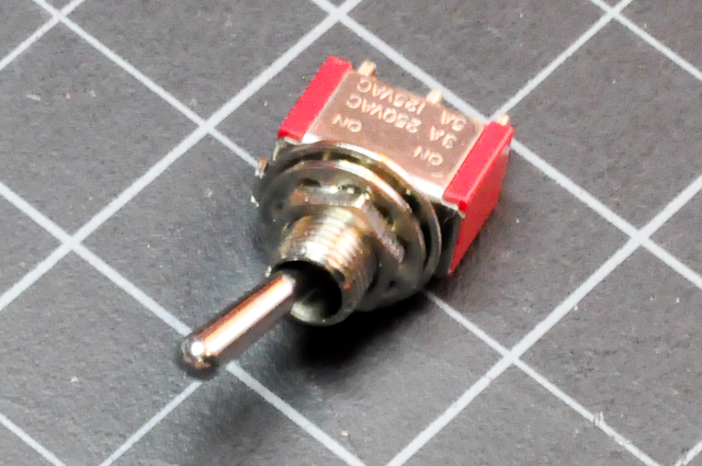
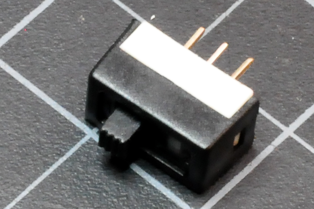
Toggle switches (Figure 10) stay closed in one physical position and open in the other. Slide switches (Figure 11) are similar to toggle switches.

Photo of a toggle switch. A component approx. 1.5cm wide by 0.5cm thick. There are three metal legs on one side, and a metal lever at the top center that can move from one side to the other. Moving the lever switches the center leg's connection from one side leg to the other.
Figure 10. Toggle switch. Moving the lever switches the center leg’s connection from one side leg to the other.
Photo of a slide switch. A component approx. 1.5cm wide by 0.5cm thick. There are three metal legs on one side, and a plastic handle at the top that can slide from one side to the other. Sliding the handle switches the center leg's connection from one side leg to the other.
Figure 11. Slide switch. Sliding the handle switches the center leg’s connection from one side leg to the other.
Photo of a magnet switch. A small plastic tube has one flat end and two wires protruding from the other end. Another tube of the same size contains a magnet. When the magnet tube's flat end is brought close to the switch tube's flat end, the connection is closed between the two wires.
Figure 12. Magnet switch.
Photo of magnet snaps. Two metal discs approx 1 inch (2.54cm) in diameter. One has a metal protrusion in the center, and the other has a depression that can fit the other's protrusion. Wires can be connected to the two snaps so that when they are snapped together, the wires are connected.
Figure 13. Magnet snaps. Used for clothing, wires can be connected to the two snaps so that when they are snapped together, the wires are connected. In this way, a garment fastener becomes a switch.

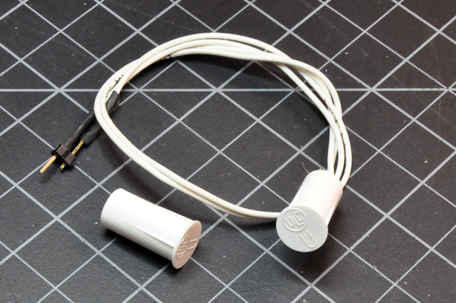
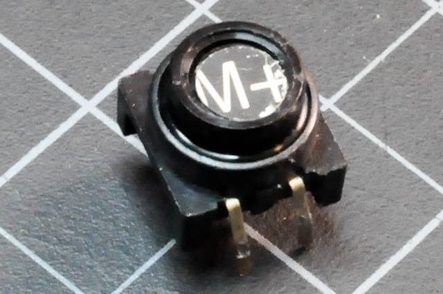
Magnetic switches (Figure 12) have two metal leaves in the end that are pulled together when a magnet is brought close to them. They’re useful when you can’t have wires on both sides of the switch mechanism. Magnetic snaps (Figure 13) are useful when you’re making a soft circuit and need a fastener on the garment to close a switch.

Photo of a whisker switch. A metal spring a few millimeters in diameter is connected to a long, thin, spring steel wire. The spring is mounted on a rubber insulation that partially covers a center post that's slightly thinner than the spring's diameter.
Figure 14. Whisker switch

Whisker switches (Figure 14) are made from a piece of spring steel or piano wire, and a center post. An insulator such as a piece of electrical tape or shrink-wrap holds the two separate. When the wire is touched, the spring bends and touches the metal post, and closes the switch.

Tilt switch. This is a small tube with metal contacts at one end and a ball inside. When the ball is tilted towards the two metal contacts, it closes the switch.
Figure 15. Tilt switch

Tilt switches (Figure 15) contain a metal ball and two wires at one end. Some tilt switches have one wire contact at each end instead. When you tilt the switch, the ball touches both contacts, and closes the switch. There are also mercury switches that do the same, but with a ball of mercury inside. Avoid these, since mercury is very poisonous.

Get Creative With Switches

A switch is nothing more than a mechanism to bring two pieces of conductive material together and separate them. You can make a switch from any two conductors and a little creativity.

Photo of a roll of grey fabric made of conductive threads.
Figure 16. Conductive fabric
Photo of copper mesh wire, approximately 4 inches (10cm) square. The mesh has holes slightly smaller than 1mm.
Figure 17. Copper mesh
Photo of a roll of copper tape, approximately 1cm thick. This tape is made of thin copper and has an adhesive backing.
Figure 18. Copper tape

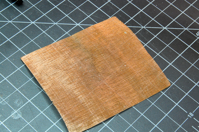
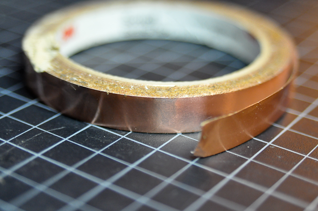
All you need to do is arrange the two conductors in such a way that they can touch or not touch. Sometimes a spacer layered between the two conductors helps. For example, in figure 19 you see three pieces of conductive material. Two of the pieces have non-conductive layers on top of them. When the non-conductive part is sandwiched between the conductive layers, you’ve got a switch that’s pressed by touching. The conductive parts touch when they’re pressed through the holes in the non-conductive part. These two switches would have different sensitivities because the hole-to-material ratio of the non-conductive layer is different.

Photo of three pieces of conductive fabric. Two of the pieces have non-conductive layers on top of them.
Figure 19. Soft switch

Make your own switch. Find a way to turn a closing door into a switch, for example, or to close a switch when a person sits down. Or figure out how to turn a hat into a switch, or a cane, or a zipper. Or perhaps the pieces of a puzzle can be switches. Come up with an everyday activity to which you can add three or four custom switches that, when combined, turn on a light. For example, maybe the light comes on when you close the door, sit down, and open a book. Or when you walk upstairs, put your keys on a side table, and remove your hat. Combine your creativity with switches with what you learned in the electronics lab and breadboard lab to make this happen. For more ideas on materials, check out How to Get What You Want. They have an excellent list of conductive materials and instructions.

Here’s mustache switch by Tak Cheung:

Arrangements of switches

Consider what happens when you arrange switches in different ways. For example, try the following circuits.

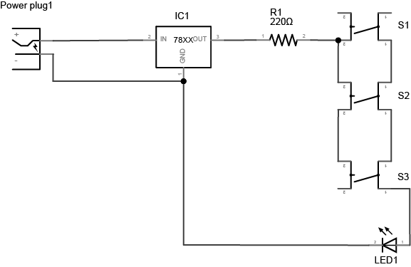
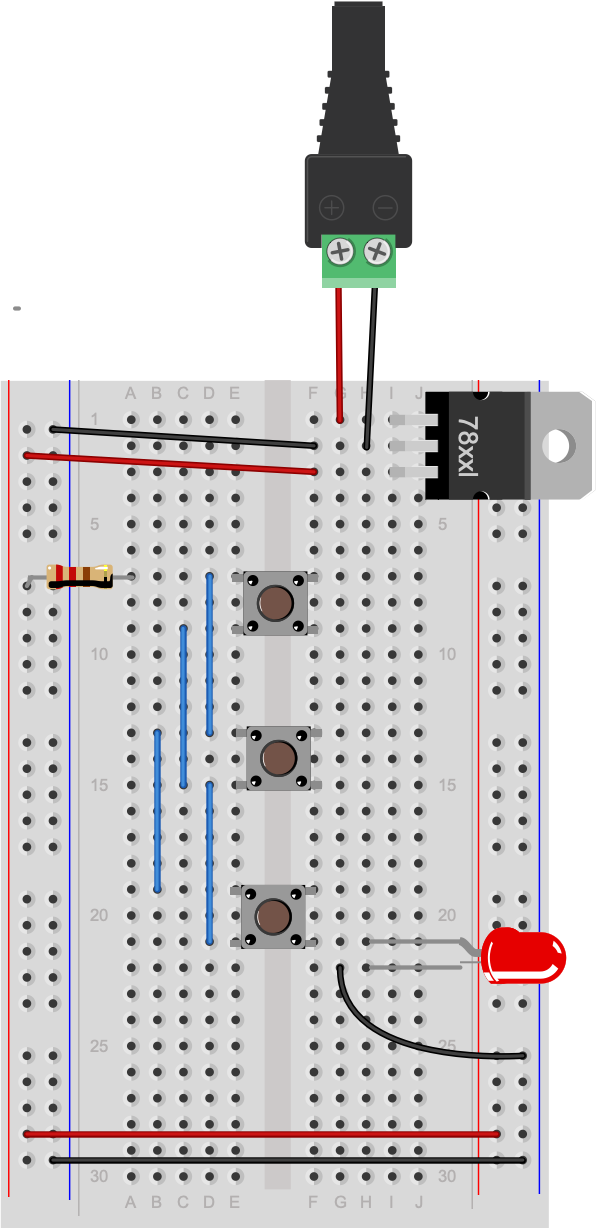
Project 1: Three switches in parallel

Three switches in parallel, as shown in Figure 20-21. Any one of the three will turn on the LED.

Drawing of three parallel switches. At the top left of the drawing there is a power supply. The positive line from the power supply connects to a 7805 5-volt voltage regulator's input. The power supply's ground is connected to the regulator's ground. The output of the regulator connects to a 220-ohm resistor. The other side of the resistor connects to one side of a switch. That side is connected to two other switches below it. The other sides of all three switches are connected to each other, and then to the anode (positive side) of an LED. The cathode (negative side) of the LED is connected to the ground of the voltage regulator.
Figure 20. Schematic view of three parallel switches connected to an LED.
Breadboard drawing of three parallel switches. At the top of the drawing,there is a DC power jack. Red and black wires from the jack connect to a 7805 5-volt voltage regulator mounted in the top right three rows of the breadboard with its tab facing to the right. input. The power supply's red wire is connected to the regulator's top pin row, the input pin. The power supply's black wire is connected to the regulator's middle pin, or ground. Another black wire connects the regulator's middle pin, ground, to the inner left side row of the board. This is the ground bus on the left side. A red wire connects the regulator's bottom pin, the output pin, to the outer left side row of the board. This is the voltage bus on the left side. At the bottom of the breadboard, a red wire connects the left side voltage bus to the inner row on the right side. This is the right side voltage bus. Similarly, a black wire connects the left side ground bus to the outer row on the right side. This is the right side ground bus. A 220-ohm resistor connects the the left side voltage bus to row 8 in the left center section of the board. A pushbutton is mounted across the center divide of the breadboard with its pins in rows 8 and 10. Another pushbutton is mounted across the center in rows 13 and 15, and a third in rows 18 and 20. In the left center section of the board, four short wires connect the top row connection of each pushbutton to the top row of the next pushbutton. Specifically: row 8 connects to row 13. Row 13 connects to row 18. Row 10 connects to row 15. Row 15 connects to row 20. In the right center section of the board, an LED's anode (long leg) is connected to row 20. The LED's cathode is connected to row 21, and a black wire connects from that row to the right side ground bus.
Figure 21. Switches in parallel, breadboard view.

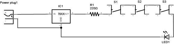
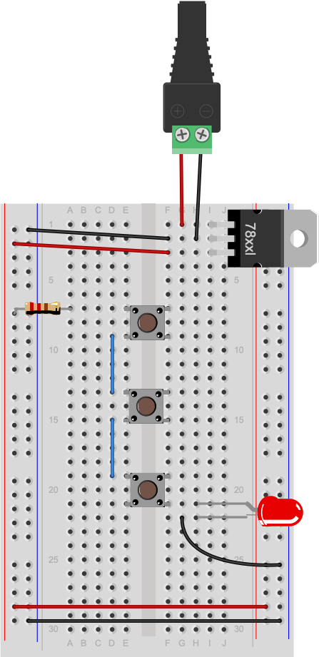
Project 2: Three switches in series

Three switches in series, as shown in Figure 22-23. All three must be on to turn on the LED.

Drawing of three switches in series. At the top left of the drawing there is a power supply. The positive line from the power supply connects to a 7805 5-volt voltage regulator's input. The power supply's ground is connected to the regulator's ground. The output of the regulator connects to a 220-ohm resistor. The other side of the resistor connects to one side of a switch. The other side of the switch connects to a second switch. The other side of that switch connects to a third switch. The other side of the third switch connects to the anode (positive side) of an LED. The cathode (negative side) of the LED is connected to the ground of the voltage regulator.
Figure 22. Schematic view of three switches in series connected to an LED.
Breadboard drawing of three switches in series connected to an LED. At the top of the drawing, there is a DC power jack. Red and black wires from the jack connect to a 7805 5-volt voltage regulator mounted in the top right three rows of the breadboard with its tab facing to the right. input. The power supply's red wire is connected to the regulator's top pin row, the input pin. The power supply's black wire is connected to the regulator's middle pin, or ground. Another black wire connects the regulator's middle pin, ground, to the inner left side row of the board. This is the ground bus on the left side. A red wire connects the regulator's bottom pin, the output pin, to the outer left side row of the board. This is the voltage bus on the left side. At the bottom of the breadboard, a red wire connects the left side voltage bus to the inner row on the right side. This is the right side voltage bus. Similarly, a black wire connects the left side ground bus to the outer row on the right side. This is the right side ground bus. A 220-ohm resistor connects the the left side voltage bus to row 8 in the left center section of the board. A pushbutton is mounted across the center divide of the breadboard with its pins in rows 8 and 10. Another pushbutton is mounted across the center in rows 13 and 15, and a third in rows 18 and 20. In the left center section of the board, two short wires connect one side of each pushbutton to the other side of the next pushbutton. Specifically: row 10 connects to row 13. Row 15 connects to row 18. In the right center section of the board, an LED's anode (long leg) is connected to row 20. The LED's cathode is connected to row 21. A black wire connects row 21 to the right side ground bus.
Figure 23. Breadboard view of three switches in series connected to an LED.

Through a combination of series and parallel switches, you can come up with a variety of combinations that make the light turn on. Depending on where you add the LEDs, you can even have the same switches turn on different LEDs in different combinations. Try a few combinations and see what happens.

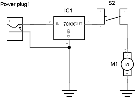
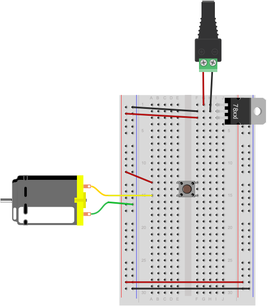
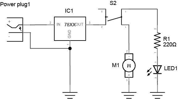
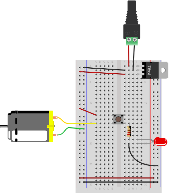
Project 3: Switching a DC motor

In a simple circuit, a DC motor* is no different than an LED as a load. You can switch it as well, as shown in Figure 24-25. Make sure your power supply can supply the current and amperage that your motor requires and you are good to go.

* DC Motor converts direct current (DC) electrical energy into mechanical energy. Check the parts and tools guide for where to get a motor. You’ll learn more about DC motors and other motors in later labs.

Drawing of a dual-pole switch controlling a motor and an LED. At the top left of the drawing there is a power supply. The positive line from the power supply connects to a 7805 5-volt voltage regulator's input. The power supply's ground is connected to the regulator's ground. The output of the regulator connects to one side of a switch. The other side of the switch connects to a DC motor. The other side of the motor connects to ground.
Figure 24. Schematic view of a DC motor switched by a pushbutton.
Breadboard drawing of a pushbutton controlling a motor. At the top of the drawing, there is a DC power jack. Red and black wires from the jack connect to a 7805 5-volt voltage regulator mounted in the top right three rows of the breadboard with its tab facing to the right. The power supply's red wire is connected to the regulator's top pin row, the input pin. The power supply's black wire is connected to the regulator's middle pin, or ground. Another black wire connects the regulator's middle pin, ground, to the inner left side row of the board. This is the ground bus on the left side. A red wire connects the regulator's bottom pin, the output pin, to the outer left side row of the board. This is the voltage bus on the left side. At the bottom of the breadboard, a red wire connects the left side voltage bus to the inner row on the right side. This is the right side voltage bus. Similarly, a black wire connects the left side ground bus to the outer row on the right side. This is the right side ground bus. A red wire connects the the left side voltage bus to row 13 in the left center section of the board. A pushbutton is mounted across the center divide of the breadboard with its pins in rows 13 and 15. A DC motor is connected to row 15 in the left center section of the board. The other wire from the motor is attached to the voltage bus on the left side of the board.
Figure 25. Breadboard view of a DC motor connected to a switch.

With a dual pole switch, you could control both a DC motor and an LED. The small square pushbuttons that come with many kits for Arduino are dual pole switches. The left side of the switch and the right side of the switch can switch different loads, like shown in Figure 26-27:

Drawing of a dual-pole switch controlling a motor and an LED. At the top left of the drawing there is a power supply. The positive line from the power supply connects to a 7805 5-volt voltage regulator's input. The power supply's ground is connected to the regulator's ground. The output of the regulator connects to one side of a switch. The other side of the switch connects to a DC motor and to a 220-ohm resistor in parallel. The other side of the motor connects to ground. The other side of the resistor connects to the anode of an LED. The other side of the LED connects to ground.
Figure 26. Schematic view of a DC motor and an LED switched by a dual-pole pushbutton (switch).
Breadboard drawing of a dual-pole pushbutton (switch) controlling a motor and an LED. At the top of the drawing, there is a DC power jack. Red and black wires from the jack connect to a 7805 5-volt voltage regulator mounted in the top right three rows of the breadboard with its tab facing to the right. input. The power supply's red wire is connected to the regulator's top pin row, the input pin. The power supply's black wire is connected to the regulator's middle pin, or ground. Another black wire connects the regulator's middle pin, ground, to the inner left side row of the board. This is the ground bus on the left side. A red wire connects the regulator's bottom pin, the output pin, to the outer left side row of the board. This is the voltage bus on the left side. At the bottom of the breadboard, a red wire connects the left side voltage bus to the inner row on the right side. This is the right side voltage bus. Similarly, a black wire connects the left side ground bus to the outer row on the right side. This is the right side ground bus. A red wire connects the the left side voltage bus to row 13 in the left center section of the board. A pushbutton is mounted across the center divide of the breadboard with its pins in rows 13 and 15. A DC motor is connected to row 15 in the left center section of the board. The other wire from the motor is attached to the voltage bus on the left side of the board. In the right center section of the board, a 220-ohm resistor is connected to row 15. The other side of the resistor is connected to row 19. The anode (long leg) of an LED is connected to row 19 as well. The cathode (short leg) of the LED is connected to row 20. A black wire connects row 20 to the right side ground bus.
Figure 27. Breadboard view of a dual-pole pushbutton (switch) controlling a DC motor and an LED.

You’ll learn more about controlling motors from a microcontroller in later labs.