Introduction
In this tutorial, you’ll learn how to control a DC motor’s direction using a DC Motor Driver.
To reverse a DC motor, you need to be able to reverse the direction of the current in the motor. The classic way to do this is using an H-bridge circuit. Though most motor driver chips these days are not in fact H-bridge circuits, the term still persists. This tutorial uses a Toshiba motor driver, the TB6612FNG, which can actually drive two DC motors. Both Sparkfun, Adafruit, and Pololu make breakout boards for the motor driver, though the Sparkfun one is shown in the examples below.
At the end of the lab, an alternative motor driver, the L9110H, is shown. This motor driver can only drive one motor at a time, unlike the TB6612FNG, but it’s more inexpensive than the TB6612FNG.
If you simply want to turn a motor on and off, and don’t need to reverse it, for example if you’re controlling a fan, try the tutorial on controlling high current loads with transistors.
What You’ll Need to Know
To get the most out of this lab, you should be familiar with the following concepts. You can check how to do so in the links below:
- Lab: Electronic components
- Lab: Digital input with Arduino
- Lab: How to use transistors to control high current loads
- Lab: How to use transistors to control high current loads with Arduino
- Video: H-Bridges
Things You’ll Need

Arduino Nano 33 IoT 
Flexible jumper wires. 
A solderless breadboard with two rows of holes along each side. 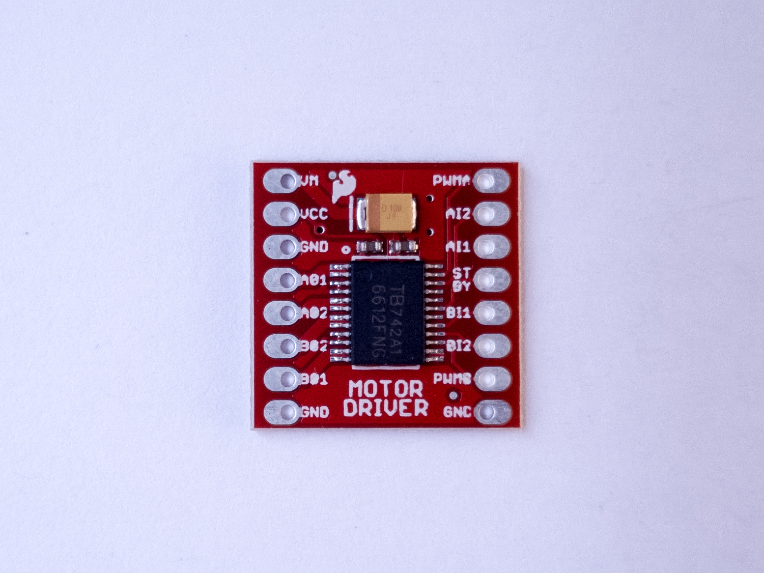
Motor Driver (H-bridge), model TB6612FNG 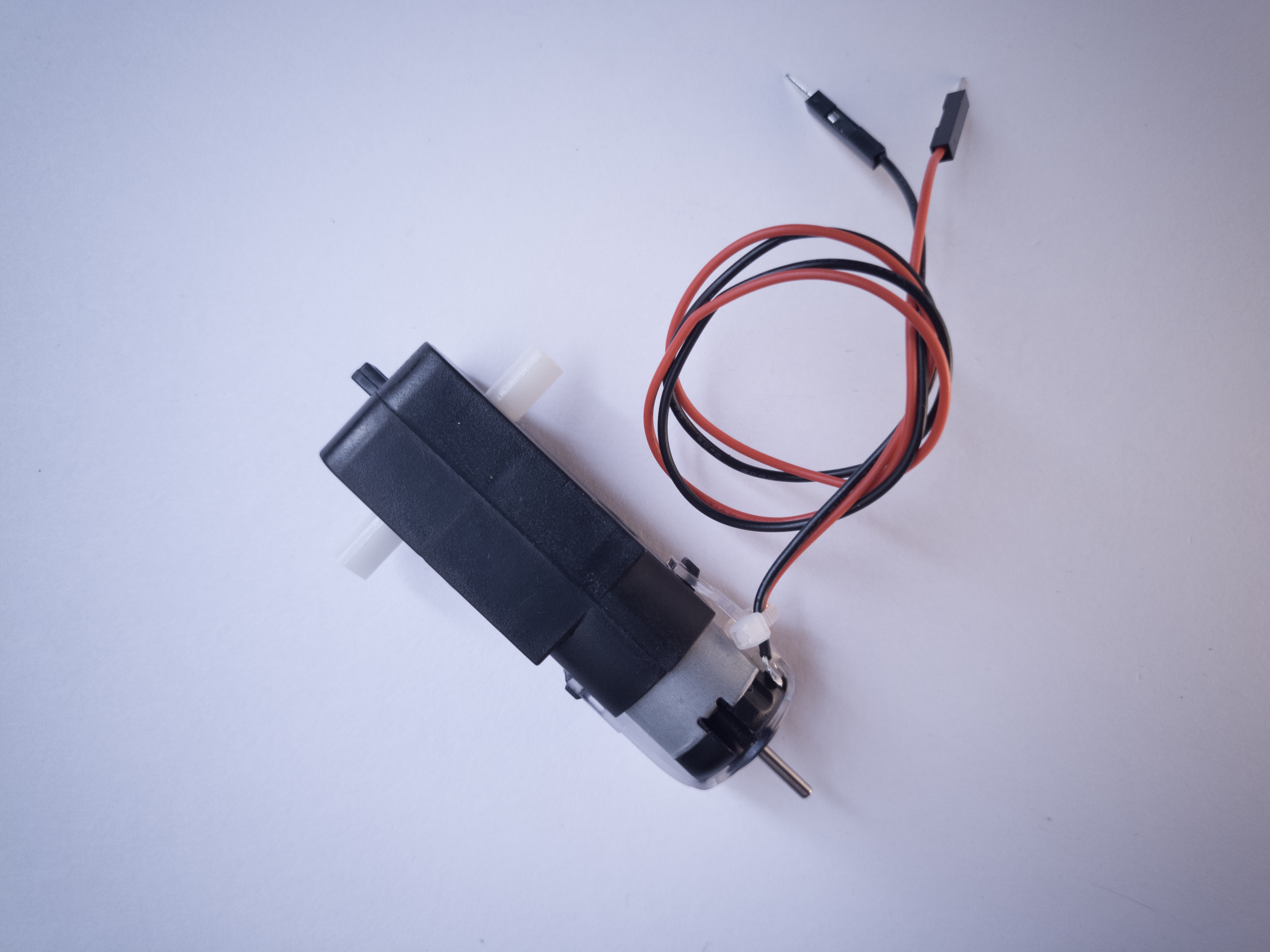
DC Gearmotor 
10-kilohm resistors. These ones are 5-band resistors 
Pushbuttons 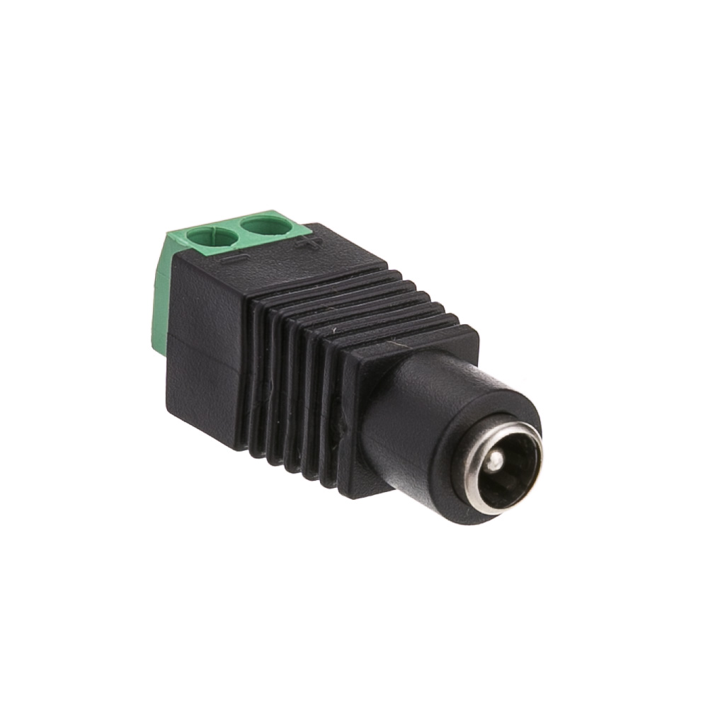
A DC Power Jack 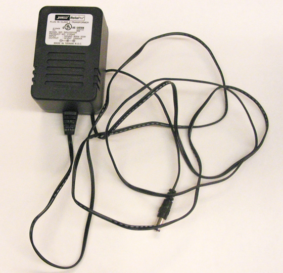
DC Power Supply
Prepare the breadboard
Connect power and ground on the breadboard to power and ground from the microcontroller. On the Arduino module, use the 5V or 3.3V (depending on your model) and any of the ground connections, as shown in Figures 10 and 11.

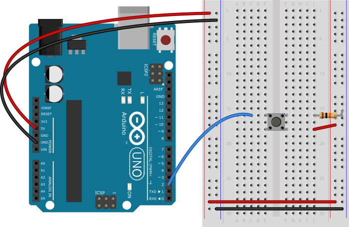
Figure 10 shows an Arduino Uno on the left connected to a solderless breadboard, right. The Uno’s 5V output hole is connected to the red column of holes on the far left side of the breadboard. The Uno’s ground hole is connected to the blue column on the left of the board. The red and blue columns on the left of the breadboard are connected to the red and blue columns on the right side of the breadboard with red and black wires, respectively. These columns on the side of a breadboard are commonly called the buses. The red line is the voltage bus, and the black or blue line is the ground bus.

As shown in Figure 11, the Nano is mounted at the top of the breadboard, straddling the center divide, with its USB connector facing up. The top pins of the Nano are in row 1 of the breadboard.
The Nano, like all Dual-Inline Package (DIP) modules, has its physical pins numbered in a U shape, from top left to bottom left, to bottom right to top right. The Nano’s 3.3V pin (physical pin 2) is connected to the left side red column of the breadboard. The Nano’s GND pin (physical pin 14) is connected to the left side black column. These columns on the side of a breadboard are commonly called the buses. The red line is the voltage bus, and the black or blue line is the ground bus. The blue columns (ground buses) are connected together at the bottom of the breadboard with a black wire. The red columns (voltage buses) are connected together at the bottom of the breadboard with a red wire.
Images made with Fritzing
Add a Digital Input (pushbutton or switch)
Connect a pushbutton to digital input 2 on the Arduino. Figure 12 shows the schematic, Figure 13 shows the breadboard view for the Uno, and Figure 14 the breadboard view for the Nano.
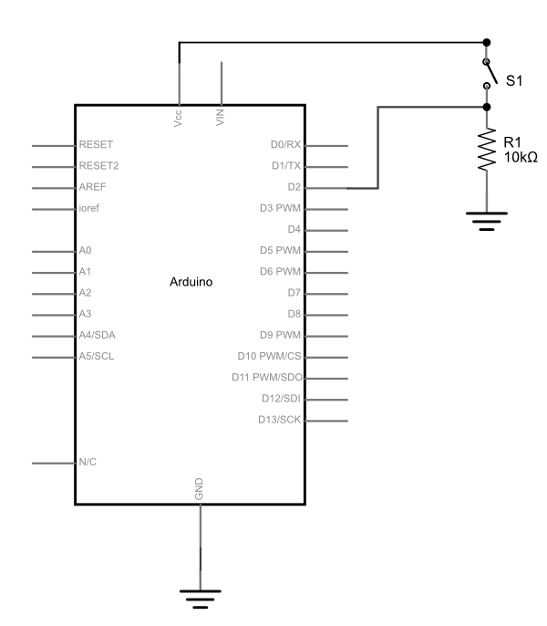
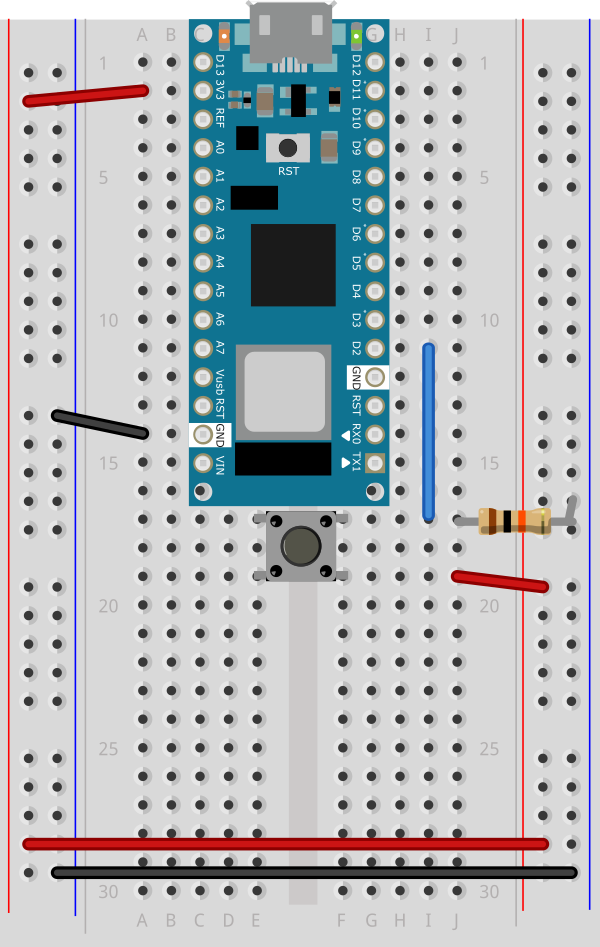
As shown in Figure 14, the Nano is mounted across the center divide of the breadboard with the USB connector pointing up. A pushbutton is mounted in across the center section of the breadboard. A red wire connects from the left side voltage bus to the lower right pin of the pushbutton. A blue wire connects the upper left pin of the pushbutton to digital pin 2 on the Arduino. A 10-kilohm resistor connects the upper right pin of the pushbutton to the ground bus on the left side of the board.
Find a motor
Find yourself a DC motor that runs on low DC voltage within the range of 3 – 15V. This one works well for this, or this one or this one. Discarded toys and printers can be good sources of these also. The ITP free store is almost always a goldmine for discarded motors and fans. Asking classmates and second years is another good approach.
Solder leads to the motor’s terminals. The motor’s direction depends on the polarity, so it’s helpful to use different colors so you know which way the motor will turn when you hook it up.
Optional: Consider testing your motor with a bench power supply from the equipment room. Ask a teacher or resident if you need help setting one up. Begin by adjusting the voltage on the bench power supply and observe its effects. Take note of its speed at different voltages without dipping to low or too high.
Safety Warning: Running a motor at a voltage much lower or much higher than what it’s rated for could potentially damage or permanently destroy your motor. When the motor doesn’t spin, the voltage is too low. When the motor runs hot, or sounds like it’s straining, the voltage is too high.
Powering Your Motor
If your motor can run on 5V (if you’re using an Uno) or 3.3V (if using a Nano 33 IoT ) and less than 500mA, you can use the Arduino’s USB voltage. Most motors require a higher voltage and higher current draw than this, however, so you will need an external power supply. You can use any DC power supply or battery up to 15V with this motor driver as long as your motor can run at that voltage, and as long as the supply can supply as much current as your motor needs. However you choose to power this circuit, make sure the power source is compatible with your motor. For example, don’t use a 9V battery for a 3V motor.
The diagrams below show how to power the motor from an external power supply. To power directly from the Arduino’s Vcc, connect the VMOT pin of the motor driver to the Vcc pin on the Arduino (5V on Uno, 3.3V on Nano)
Set up the Motor Driver
This tutorial uses a Toshiba motor driver, the TB6612FNG, which can actually drive two motors.There’s a Sparkfun breakout board, an Adafruit breakout board, and a Pololu breakout board for this part as well.
How The Motor Driver Works
The TB6612FNG can handle a motor supply voltage up to 15V, and it operates on a logic voltage of 2.7–5.5V. It can control an output current of 1.2A. It has two motor driver circuits, each with two logic inputs and two motor outputs. Each motor driver has a PWM input, because they are expected to be used for speed control for the motor by pulse width modulating this pin. There’s also a Standby pin that you have to connect to voltage through a 10-kilohm pullup resistor to activate the motor driver circuits.
The motor driver has the following pins. The pin numbers shown here are for the Sparkfun breakout board. The order of the pins will be different for the Adafruit and Pololu boards. The Pins are numbered here in a DIP fashion, in a U-shape from top left to bottom left, then bottom right to top right.
- VMOT – motor voltage supply input, up to 15V.
- Vcc – logic voltage supply input, 2.7-5.5V
- Gnd – ground
- AO1 – A channel output 1. This is the first motor terminal for the first motor driver
- AO2 – A channel output 2. This is the second motor terminal for the first motor driver
- BO2 – B channel output 2. This is the second motor terminal for the second motor driver
- BO1 – B channel output 1. This is the first motor terminal for the second motor driver
- Gnd – ground
- Gnd – ground
- PWMB – B Channel PWM Enable. This pin controls the speed for channel B, regardless of the channel’s direction
- BI2 – B channel input 2. This controls B channel output 2. To control that pin, take this pin HIGH or LOW.
- BI1 – B channel input 1. This controls B channel output 1. To control that pin, take this pin HIGH or LOW.
- Stdby – enables both drivers when you take it HIGH and disables them when you take it LOW
- AI1 – A channel input 1. This controls A channel output 1. To control that pin, take this pin HIGH or LOW.
- AI2 – A channel input 2. This controls A channel output 2. To control that pin, take this pin HIGH or LOW.
- PWMA – A Channel PWM Enable. This pin controls the speed for channel A, regardless of the channel’s direction
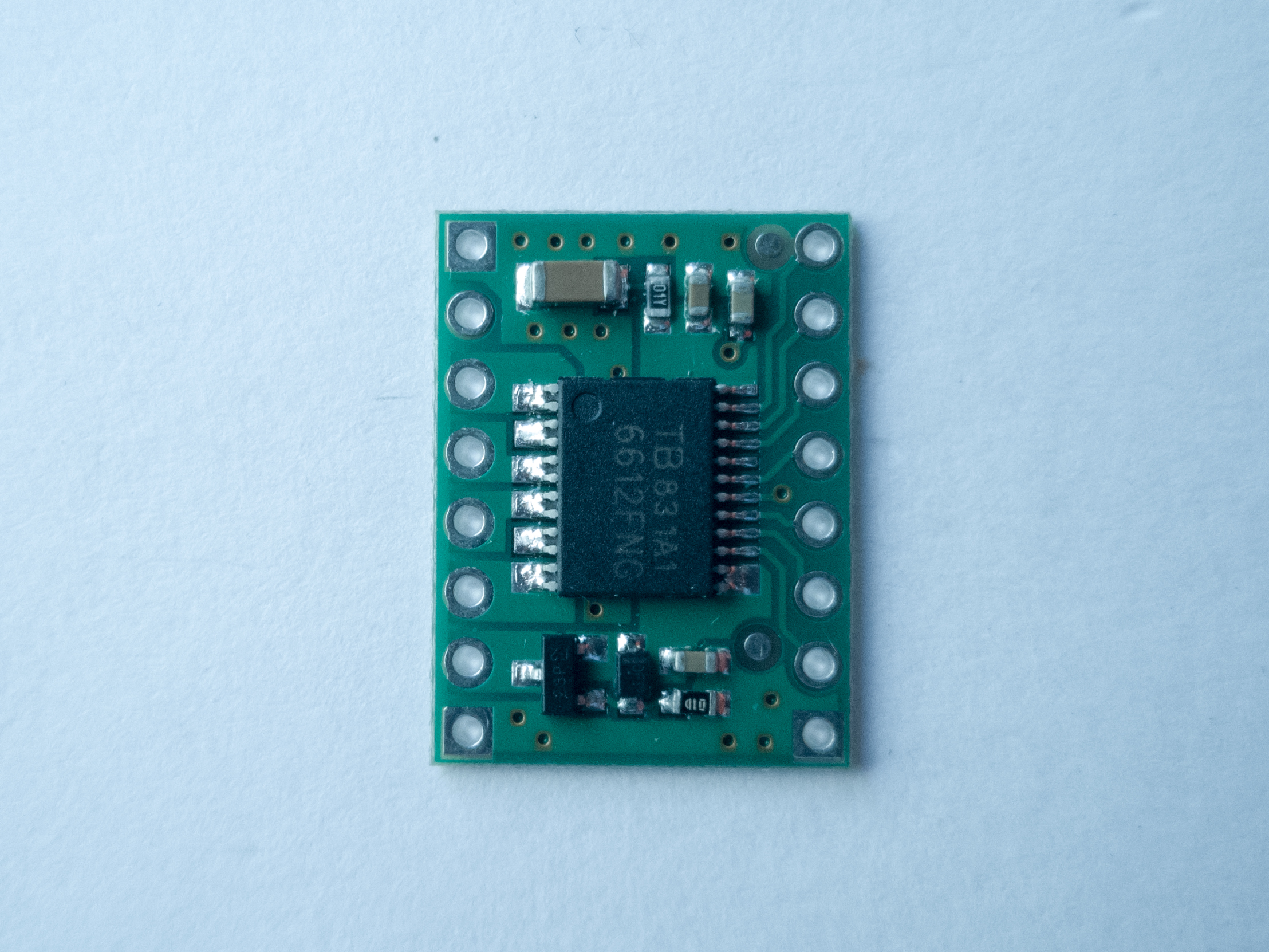
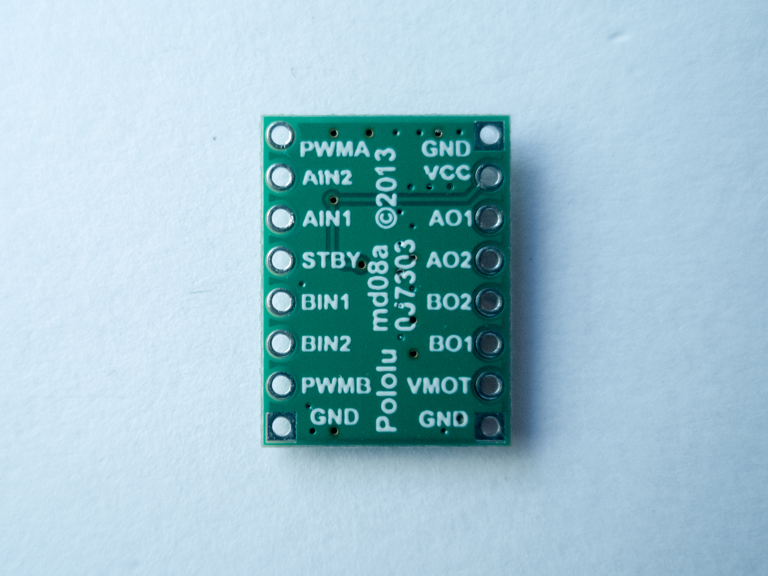
Figure 15 shows the Sparkfun board, and Figures 16 and 17 show the Pololu board front and back. The Pololu board is labeled on the back. You can see that both boards have the same pins, even though the layouts are different.
You can change the direction and speed of the motor using the motor driver. The truth table below shows how the motor driver works.
| AI1 | AI2 | PWMA | Effect |
|---|---|---|---|
| H | L | H | Motor turns one direction |
| L | H | H | Motor turns the other direction |
| L | L | – | Motor stop |
| H | H | – | Motor stop |
| – | – | L | Motor stop |
For this lab, the PWMA pin connects to a digital pin on your Arduino so you can send it either HIGH or LOW and turn the motor ON or OFF, or pulse width modulate it to control the speed. The motor logic pins are also connected to designated digital pins on your Arduino so you can set them HIGH and LOW to turn the motor in one direction, or LOW and HIGH to turn it in the other direction. The motor supply voltage connects to the voltage source for the motor, which is usually an external power supply.
Connect the motor to the Driver
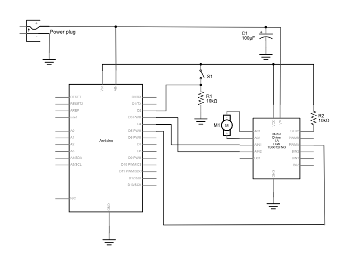
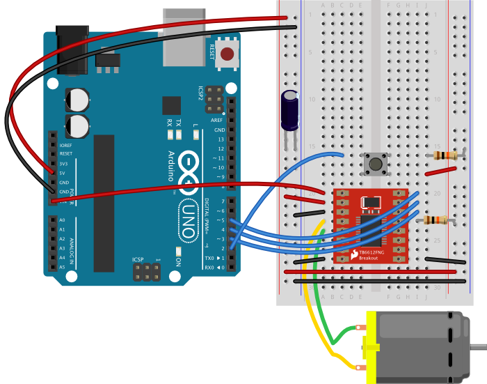
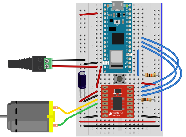
Connect the motor to the driver as shown in Figures 18 – 20. Figure 18 shows the schematic, Figure 19 shows the breadboard view for an Uno, and Figure 20 shows the breadboard view for a Nano.
Note on decoupling capacitors
If you find that your microcontroller is resetting whenever the motor turns on, add a capacitor across power and ground close to the motor. The capacitor will smooth out the voltage dips that occur when the motor turns on. This use of a capacitor is called a decoupling capacitor. Usually a 10 – 100uF capacitor will work. The larger the cap, the more charge it can hold, but the longer it will take to release its charge.
Program the microcontroller
Program the microcontroller to run the motor through the driver. First set up constants for the switch pin, the two motor driver pins, and the PWM enable pin of the motor driver. Use pin 5, one of the pins that can produce a PWM signal using analogWrite(), for the PWM enable pin.
const int switchPin = 2;    // switch input
const int motor1Pin = 3;    // Motor driver leg 1 (pin 3, AIN1)
const int motor2Pin = 4;    // Motor driver leg 2 (pin 4, AIN2)
const int pwmPin = 5;       // Motor driver PWM pin
In the setup(), set all the pins for the motor driver as outputs, and the pin for the switch as an input. Then set the PWM enable pin high so the driver can turn the motor on.
void setup() {
    // set the switch as an input:
    pinMode(switchPin, INPUT);

    // set all the other pins you're using as outputs:
    pinMode(motor1Pin, OUTPUT);
    pinMode(motor2Pin, OUTPUT);
    pinMode(pwmPin, OUTPUT);

    // set PWM enable pin high so that motor can turn on:
    digitalWrite(pwmPin, HIGH);
  }
In the main loop() read the switch. If it’s high, turn the motor one way by taking one motor driver pin high and the other low. If the switch is low, reverse the direction by reversing the states of the two pins.
void loop() {
    // if the switch is high, motor will turn on one direction:
    if (digitalRead(switchPin) == HIGH) {
      digitalWrite(motor1Pin, LOW);   // set leg 1 of the motor driver low
      digitalWrite(motor2Pin, HIGH);  // set leg 2 of the motor driver high
    }
    // if the switch is low, motor will turn in the other direction:
    else {
      digitalWrite(motor1Pin, HIGH);  // set leg 1 of the motor driver high
      digitalWrite(motor2Pin, LOW);   // set leg 2 of the motor driver low
    }
  }
Once you’ve seen this code working, try modifying the speed of the motor using the analogWrite() function, as explained in the Analog Lab. Use analogWrite() on the PWM enable pin of the motor, and see what happens as you change the value of the analogWrite().
An Alternative Motor Driver
If you don’t have a TB6612FNG motor driver, or if you want something simpler and less expensive, the L9110H driver will also control a DC motor’s direction and speed. It can handle and input voltage of 2.5V-12V at 800mA of current. It can drive only one motor, unlike the TB6612FNG, and it can’t control stepper motors like that driver can. But it is inexpensive.
THe L9110H comes in an 8-pin DIP package. There are two inputs, labeled the A and B channels, and they are connected to two outputs, also labeled A and B. Your motor connects to the outputs and your control pins connect to the inputs. Vcc connects to the motor supply and GND connects to ground. Its pins, numbered from top left in a U shape as usual, are as follows:
- OA – output for the A channel
- Vcc – motor supply voltage
- Vcc – motor supply voltage
- OB output for the B channel
- GND – ground
- IA – input for the A channel
- IB – input for the B channel
- GND – ground
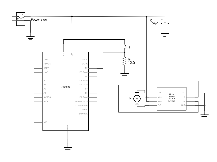
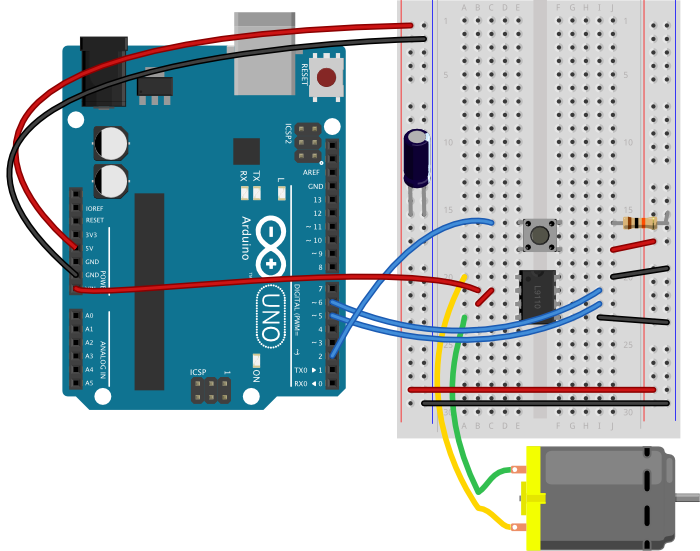
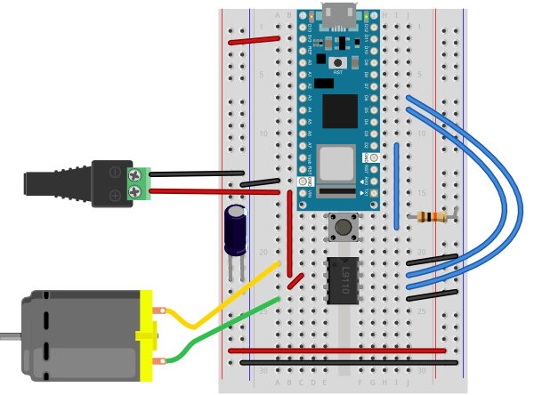
Figure 21 shows the schematic, and Figures 22 and 23 show it connected to an Uno and a Nano 33 IoT, respectively.
To control the motor, you take one input high and the other low, just like with the previous motor driver. Since this driver has no PWM pin, you have to pulsewidth modulate the high input to manage speed control, though.
The program below controls the L9110H, setting the speed to about half the maximum whenever you push the button. To make a variable speed you could add a potentiometer and change the value of the speed variable using the potentiometer.
const int switchPin = 2;  // pushbutton input
const int motor1Pin = 5;  // H-bridge leg 1 (pin 6, 1A)
const int motor2Pin = 6;  // H-bridge leg 2 (pin 7, 2A)

// speed of the motor (0-255):
int speed = 127;

void setup() {
  // set the pushbutton as an input:
  pinMode(switchPin, INPUT);

  // set all the other pins you're using as outputs:
  pinMode(motor1Pin, OUTPUT);
  pinMode(motor2Pin, OUTPUT);
}

void loop() {
  // if the pushbutton is high, motor will turn on one direction:
  if (digitalRead(switchPin) == HIGH) {
    // set leg 1 of the H-bridge low:
    digitalWrite(motor1Pin, LOW);
    // set leg 2 of the H-bridge high:
    analogWrite(motor2Pin, speed);
  }
  // if the pushbutton is low, motor will turn in the other direction:
  else {
    // set leg 1 of the H-bridge high:
    digitalWrite(motor1Pin, speed);
    // set leg 2 of the H-bridge low:
    digitalWrite(motor2Pin, LOW);
  }
}
Get creative
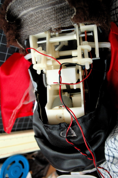
Motors can be used to make things move, vibrate, rise, fall, roll, creep, or whatever you can think of, in response to user input from a digital input device (switch, floor sensor, tripwire, etc). Look inside moving toys, you’ll find a number of excellent motors and gears you can re-purpose. See the innards of a cymbal monkey below as an example. Perhaps you can re-design the user interface to a toy, using the microcontroller to mediate between new sensors on the toy and the motors of the toy.
If you used a motor in this lab, consider any toys you have that have a motor you could take control over. Charley Chimp™ has a motor that’s easy to control from an Arduino, for example.
You could also consider simple movements in the work of artists like Jennifer Townley, Johannes Langenkamp (instagram), Nick Yulman, or Lu Lyu.