Introduction
This lab covers only the details of MIDI communication on the Arduino module. For a more general introduction to MIDI on a microprocessor, see the the MIDI notes.
MIDI, the Musical Instrument Digital Interface, is a useful protocol for controlling synthesizers, sequencers, and other musical devices. MIDI devices are generally grouped in to two broad classes: controllers (i.e. devices that generate MIDI signals based on human actions) and synthesizers (including samplers, sequencers, and so forth). The latter take MIDI data in and make sound, light, or some other effect.
What You’ll Need to Know
To get the most out of this lab, you should be familiar with the following concepts. You can check how to do so in the links below:
- How to Solder a connector
- Digital Input with Arduino
- Analog Input with Arduino
- What is an Arduino Library
- How to communicate serially with the Arduino and how to send values serially in different formats
Things You’ll Need
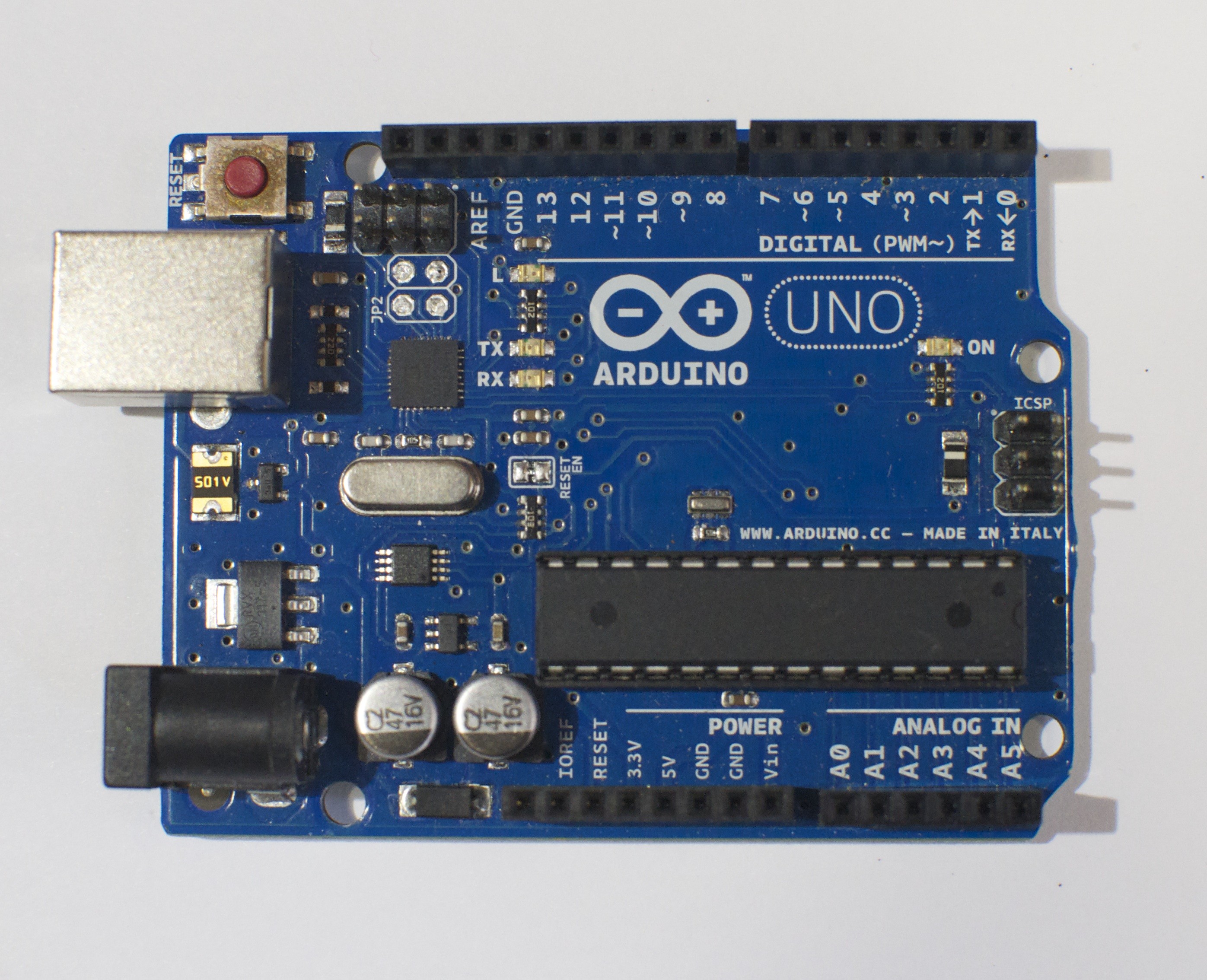
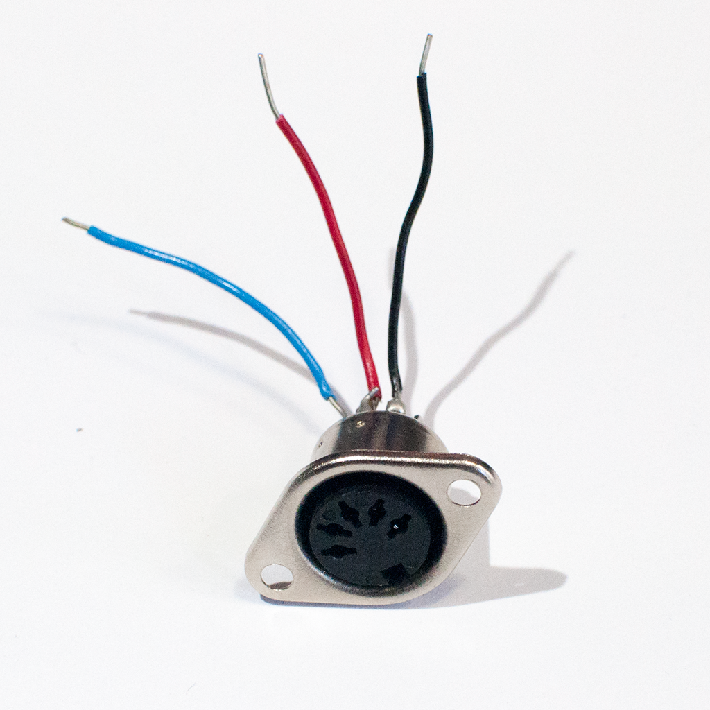
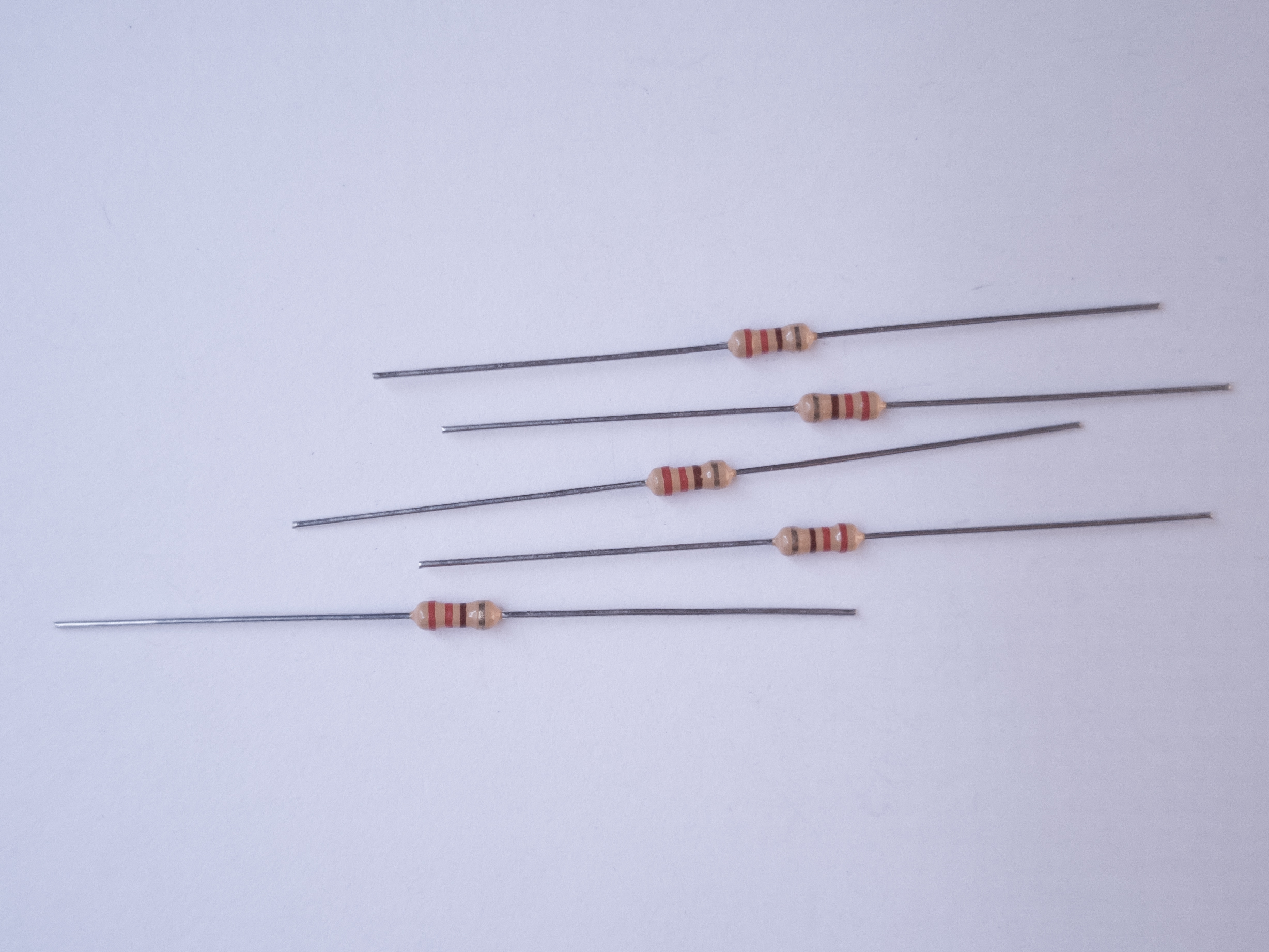
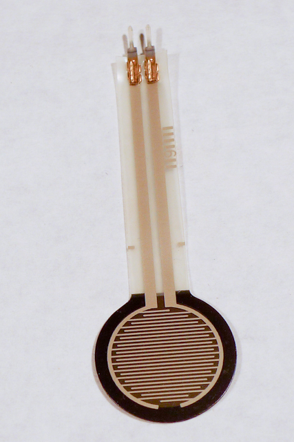
Figure 1-9 are the parts that you need for this lab.


MIDI appoaches: Serial, SoftwareSerial, or MIDIUSB
There are three approaches you can take to MIDI output, depending on the board you’re using and the application you have in mind.
If you’re communicating with a MIDI sound module like a synthesizer or sampler, you’ll need to use either Serial or SoftwareSerial output. On the Uno, SoftwareSerial is best. On most other Arduino models, there is a second hardware serial port, Serial1, that you can use for MIDI output.
If you’re communicating with a MIDI program like Ableton, GarageBand, or a soundFont synth like Sforzando, either on a laptop or mobile device, then MIDIUSB is the way to go. The Uno can’t communicate using MIDIUSB, but the Nano 33 IoT, the MKR series, the Leonardo, Micro, or Due can.
SoftwareSerial Approach
If you’re using an Uno or any board with only one serial port, the SoftwareSerial library is your best bet. This section describes how to wire and program your board for SoftwareSerial.
Prepare the breadboard
Connect power and ground on the breadboard to power and ground from the microcontroller. On the Arduino module, use the 5V and any of the ground connections (Figure 10):

Made with Fritzing
For the Nano 33 IoT version or any of the MIDIUSB versions (see below), you won’t need a MIDI jack.
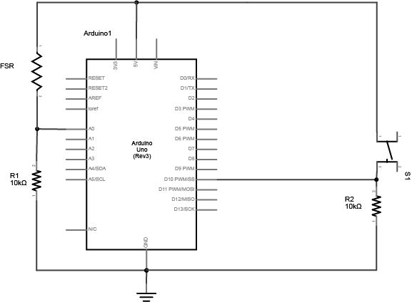
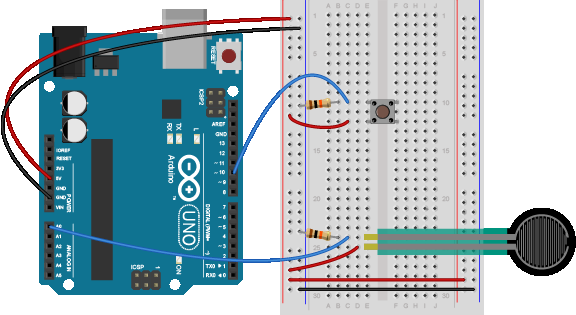
Connect the sensors
Connect an analog sensor to analog pins 0 like you did in the analog lab (Figure 11). Connect a switch to digital pin 10 like you did in the digital lab (Figure 12).
Build the MIDI Circuit
Add the MIDI out jack and a 220-ohm resistor to digital pin 3, as shown in Figure 13-14:
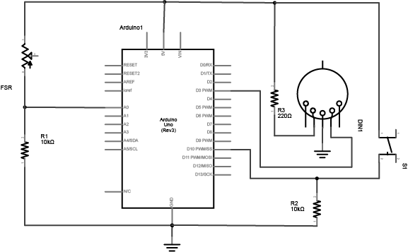
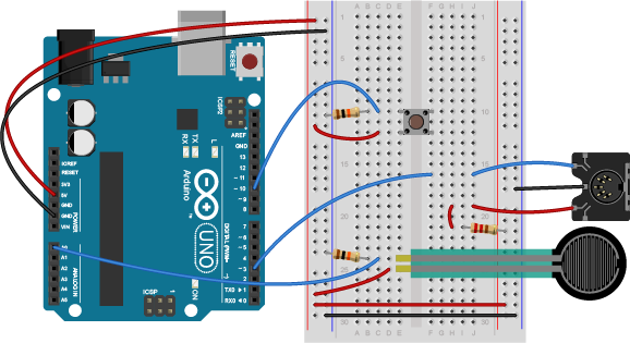
This circuit doesn’t actually match the MIDI specification, but it works with all the MIDI devices we’ve tried it with. This circuit includes an analog and a digital sensor to allow for physical interactivity, but those aren’t necessary to send MIDI data.
Play Notes
Once you’re connected, sending MIDI is just a matter of sending the appropriate bytes. In the code below, you’ll use the SoftwareSerial library to send data on digital pin 3, so that you can keep the hardware serial available for debugging purposes.
The bytes have to be sent as binary values, but you can format them in your code as decimal or hexadecimal values. The example below uses hexadecimal format for any fixed values, and a variable for changing values. All values are sent serially as raw binary values, using the BYTE modifier to .print() (Many MIDI tables give the command values in hex, so this was done in hex for the sake of convenience):
#include"SoftwareSerial.h"

 // Variables:
  byte note = 0;            // The MIDI note value to be played

 //software serial
 SoftwareSerial midiSerial(2, 3); // digital pins that we'll use for soft serial RX and TX

  void setup() {
    //  Set MIDI baud rate:
    Serial.begin(9600);
    midiSerial.begin(31250);
  }

  void loop() {
    // play notes from F#-0 (30) to F#-5 (90):
    for (note = 30; note < 90; note ++) {
      //Note on channel 1 (0x90), some note value (note), middle velocity (0x45):
      noteOn(0x90, note, 0x45);
      delay(100);
      //Note on channel 1 (0x90), some note value (note), silent velocity (0x00):
      noteOn(0x90, note, 0x00);
      delay(100);
    }
  }

  //  plays a MIDI note.  Doesn't check to see that
  //  cmd is greater than 127, or that data values are  less than 127:
  void noteOn(byte cmd, byte data1, byte data2) {
    midiSerial.write(cmd);
    midiSerial.write(data1);
    midiSerial.write(data2);

     //prints the values in the serial monitor so we can see what note we're playing
    Serial.print("cmd: ");
    Serial.print(cmd);
    Serial.print(", data1: ");
    Serial.print(data1);
    Serial.print(", data2: ");
    Serial.println(data2);
  }
Alternatives to SoftwareSerial
There are two alternatives to SoftwareSerial, but they are only available on boards other than the Uno. You could use the second hardware serial port if you have one. Or, if you’re using one of the MKR series boards or a Nano 33 IoT or an M0-based derivative board, you can use MIDIUSB.
Second Hardware Serial Port
If you’re using any board that has two hardware serial ports, you don’t have to use SoftwareSerial. That includes almost any of the official Arduino boards except the Uno: the Nano 33 IoT, the Due, the Mega, the MKR series, the Leonardo, the Micro and the 101 all have two hardware serial ports. You could also use any M0- or 32U4-based derivative board like Adafruit’s Feather and Trinket boards. If you are using one of those boards, copy the circuits above but move the MIDI connector’s pin 4 to the TX1 pin of your board. Then change your code as follows. First, remove the first line that includes the SoftwareSerial library. Then remove the line that initializes SoftwareSerial. Then change midiSerial.begin() to Serial1.begin(). Then change all midiSerial calls to Serial1 calls. Here’s the changed code:
// Variables:
byte note = 0; // The MIDI note value to be played

void setup() {
  // Set MIDI baud rate:
  Serial.begin(9600);
  Serial1.begin(31250);
}

void loop() {
  // play notes from F#-0 (30) to F#-5 (90):
  for (note = 30; note < 90; note ++) {
    // Note on channel 1 (0x90), some note value (note), middle velocity (0x45):
    noteOn(0x90, note, 0x45);
    delay(100);
    // Note on channel 1 (0x90), some note value (note), silent velocity (0x00):
    noteOn(0x90, note, 0x00);
    delay(100);
  }
}

// plays a MIDI note. Doesn't check to see that
// cmd is greater than 127, or that data values are less than 127:
void noteOn(byte cmd, byte data1, byte data2) {
  Serial1.write(cmd);
  Serial1.write(data1);
  Serial1.write(data2);

  //prints the values in the serial monitor so we can see what note we're playing
  Serial.print("cmd: ");
  Serial.print(cmd);
  Serial.print(", data1: ");
  Serial.print(data1);
  Serial.print(", data2: ");
  Serial.println(data2);
}
Using MIDIUSB
If you’re using an ARM board like the MKR series, the Nano 33 IoT, the Due, or any of the M0-based derivatives, you can also use MIDIUSB. When you do this, your microcontroller shows up to your computer like a USB MIDI device. This is handy for when you’re connecting to a laptop. It’s less handy for connecting to dedicated synthesizers or samplers.
To do this, dispose of the MIDI socket. You’ll be connecting through your USB connector, and yes, the serial connection to the Serial Monitor will still work as well. Change your code as follows. First include the MIDIUSB library (you might need to install it using the Library Manager) at the top of your code. Then remove the Serial1.begin() line in the setup. Then replace the Serial1.write() lines in the noteOn function with the MIDI code shown below:
  #include "MIDIUSB.h"
  // Variables:
  byte note = 0;            // The MIDI note value to be played

  void setup() {
    Serial.begin(9600);
  }

  void loop() {
    // play notes from F#-0 (30) to F#-5 (90):
    for (note = 30; note < 90; note ++) {
      //Note on channel 1 (0x90), some note value (note), middle velocity (0x45):
      noteOn(0x90, note, 0x45); delay(100);
      //Note on channel 1 (0x90), some note value (note), silent velocity (0x00):
      noteOn(0x90, note, 0x00); delay(100);
     }
   }

   // plays a MIDI note. Doesn't check to see that
   // cmd is greater than 127, or that data values are less than 127:
   void noteOn(byte cmd, byte data1, byte data2) {
     /* First parameter is the event type (top 4 bits of the command byte).
        Second parameter is command byte combined with the channel.
        Third parameter is the first data byte
        Fourth parameter second data byte, if there is one:
    */
    midiEventPacket_t midiMsg = {cmd >> 4, cmd, data1, data2};
    MidiUSB.sendMIDI(midiMsg);

    //prints the values in the serial monitor so we can see what note we're playing
    Serial.print("cmd: ");
    Serial.print(cmd);
    Serial.print(", data1: ");
    Serial.print(data1);
    Serial.print(", data2: ");
    Serial.println(data2);
  }
Note on MIDIUSB and Serial Ports
The MIDIUSB library on the SAMD boards (MKRZero, MKR1xxx, Nano 33IoT) has an unusual behavior: using it changes the serial port enumeration. When you include the MIDIUSB library in a sketch, your board’s serial port number will change. For example, on MacOS, if the port number is /dev/cu.usbmodem14101, then adding the MIDIUSB library will change it to /dev/cu.usbmodem14102. Removing the MIDIUSB library will change it back to /dev/cu.usbmodem14101. Similarly, if you double-tap the reset button to put the board in bootloader mode, the serial port will re-enumerate to its original number.
Windows and MIDIUSB
You may have trouble getting these MIDI sketches to work on Windows. On Windows, the default Arduino drivers must be uninstalled so the system can recognize the Arduino as both serial device and MIDI device. Read this issue and follow the instructions there.
Allow a Person to Play Notes
The previous example will just play notes, no interactivity. The example below uses an analog input to set the pitch, and a digital input (a switch) to start and stop the note:
 #include "SoftwareSerial.h"

 const int switchPin = 10;  // The switch is on Arduino pin 10
 const int LEDpin = 13;     //  Indicator LED

  // Variables:
  byte note = 0;              // The MIDI note value to be played
  int AnalogValue = 0;        // value from the analog input
  int lastNotePlayed = 0;     // note turned on when you press the switch
  int lastSwitchState = 0;    // state of the switch during previous time through the main loop
  int currentSwitchState = 0;

 //software serial
 SoftwareSerial midiSerial(2, 3); // digital pins that we'll use for soft serial RX and TX

  void setup() {
    //  set the states of the I/O pins:
    pinMode(switchPin, INPUT);
    pinMode(LEDpin, OUTPUT);
    //  Set MIDI baud rate:
    Serial.begin(9600);
    midiSerial.begin(31250);
  }

  void loop() {
    //  My potentiometer gave a range from 0 to 1023:
    AnalogValue = analogRead(0);
    //  convert to a range from 0 to 127:
    note = AnalogValue/8;
    currentSwitchState = digitalRead(switchPin);
    // Check to see that the switch is pressed:
    if (currentSwitchState == 1) {
      //  check to see that the switch wasn't pressed last time
      //  through the main loop:
      if (lastSwitchState == 0) {
        // set the note value based on the analog value, plus a couple octaves:
        // note = note + 60;
        // start a note playing:
        noteOn(0x90, note, 0x40);
        // save the note we played, so we can turn it off:
        lastNotePlayed = note;
        digitalWrite(LEDpin, HIGH);
      }
    }
    else {   // if the switch is not pressed:
      //  but the switch was pressed last time through the main loop:
      if (lastSwitchState == 1) {
        //  stop the last note played:
        noteOn(0x90, lastNotePlayed, 0x00);
        digitalWrite(LEDpin, LOW);
      }
    }

    //  save the state of the switch for next time
    //  through the main loop:
    lastSwitchState = currentSwitchState;
  }

  //  plays a MIDI note.  Doesn't check to see that
  //  cmd is greater than 127, or that data values are  less than 127:
  void noteOn(byte cmd, byte data1, byte  data2) {
    midiSerial.write(cmd);
    midiSerial.write(data1);
    midiSerial.write(data2);

   //prints the values in the serial monitor so we can see what note we're playing
    Serial.print("cmd: ");
    Serial.print(cmd);
    Serial.print(", data1: ");
    Serial.print(data1);
    Serial.print(", data2: ");
    Serial.println(data2);
  }
Make an Instrument
Now that you’ve got the basics, make a musical instrument. Consider a few things in designing your instrument:
- Do you want to play discrete notes (like a piano), or sliding pitches (like a theremin)? How do you program to achieve these effects?
- Do you want to control the tempo and duration of a note?
- Do you want the same physical action to set both the pitch and the velocity (volume) of a note?
- Do you want to be able to play more than one note at a time (e.g. chords)?
All of these questions, and many more, will affect what sensors you use, how you read them, and how you design both the physical interface and the software.
For more on MIDI, music, and instruments, see these notes, and this overview of MIDI on the Arduino.