Introduction
In this tutorial, you’ll learn how to control a high-current DC load such as a DC motor or an incandescent light from a microcontroller. Microcontrollers can only output a very small amount of current from their output pins. These pins are meant to send control signals, not to act as power supplies. The most common way to control another direct current device from a microcontroller is to use a transistor. Transistors allow you to control the flow of a high-current circuit from a low-current source.
- Video: Transistor Schematics
- Video: Meet the motors
- Video: Pulse-width modulating a transistor to to control a fan motor
- Video: NPN Transistors
- Video: Darlingtons and MOSFETs
What You’ll Need to Know
To get the most out of this Lab you should be familiar with the following concepts beforehand. If you’re not, review the links below:
- What is a microcontroller
- Beginning programming terms
- What is a solderless breadboard and how to use one
- Digital Input and output
- Analog Output
- Basic Electronics
- Safety Warning: This tutorial shows you how to control high-current loads. This comes with a higher danger of injury from electricity than the earlier tutorials. Please be careful and double-check your wiring before plugging anything in, and never change your wiring while your circuit is powered.
Things You’ll Need


Prepare the breadboard
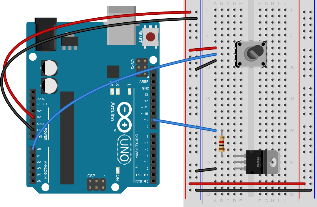
Connect power and ground on the breadboard to power and ground from the microcontroller. On the Arduino module, use the 5V or 3.3V (depending on your model) and any of the ground connections, as shown in Figures 11 and 12.

Figure 11 shows an Arduino Uno on the left connected to a solderless breadboard, right. The Uno’s 5V output hole is connected to the red column of holes on the far left side of the breadboard. The Uno’s ground hole is connected to the blue column on the left of the board. The red and blue columns on the left of the breadboard are connected to the red and blue columns on the right side of the breadboard with red and black wires, respectively. These columns on the side of a breadboard are commonly called the buses. The red line is the voltage bus, and the black or blue line is the ground bus.

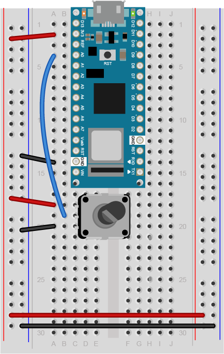
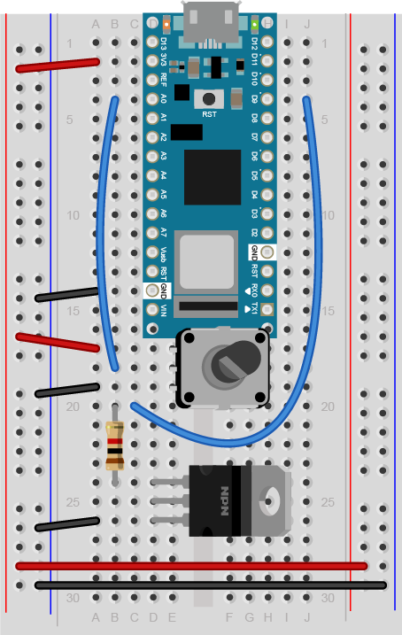
As shown in Figure 12, the Nano is mounted at the top of the breadboard, straddling the center divide, with its USB connector facing up. The top pins of the Nano are in row 1 of the breadboard.
The Nano, like all Dual-Inline Package (DIP) modules, has its physical pins numbered in a U shape, from top left to bottom left, to bottom right to top right. The Nano’s 3.3V pin (physical pin 2) is connected to the left side red column of the breadboard. The Nano’s GND pin (physical pin 14) is connected to the left side black column. These columns on the side of a breadboard are commonly called the buses. The red line is the voltage bus, and the black or blue line is the ground bus. The blue columns (ground buses) are connected together at the bottom of the breadboard with a black wire. The red columns (voltage buses) are connected together at the bottom of the breadboard with a red wire.
Images made with Fritzing
Add a potentiometer
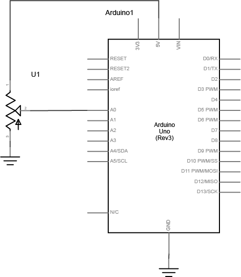
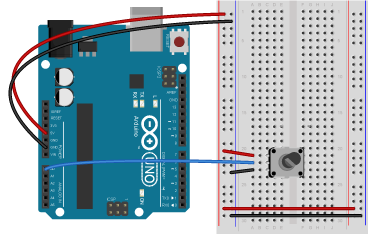
Connect a potentiometer to analog in pin 0 of the module as shown in Figure 13 through Figure 15:
Connect a Transistor to the Microcontroller
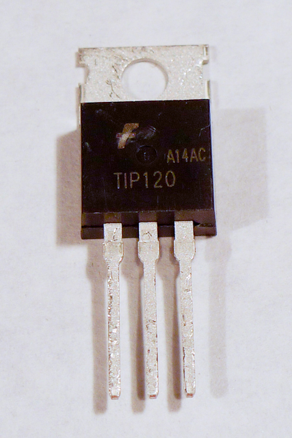
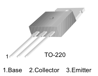
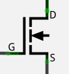
The transistor allows you to control a circuit that’s carrying higher current and voltage from the microcontroller. It acts as an electronic switch. You can use a bipolar Darlington transistor like the TIP120, or you can use a MOSFET like the IRF520 or FQP30N06L for this lab. All three will work the same way and use the same circuit. See Figures 16 through Figure 19 for the drawings and schematic symbols of the transistors.

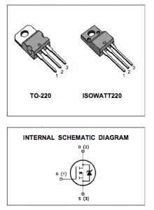
The IRF520 MOSFET has the same pin configuration as the TIP120, and performs similarly with a 5V gate voltage. The FQP30N06L MOSFET has the same pin configuration, and operates on as low as 1.0V, and works well for 3.3V applications. MOSFETs can generally handle more amperage and voltage, and switch a little faster (the difference is in microseconds, so you won’t notice), but they are more sensitive to static electricity damage. They are grouped into N-Channel and P-Channel, which are equivalent to NPN and PNP bipolar transistors.
All three transistors mentioned here are designed for switching high-current loads. All of them have built-in protection diodes. Each has three connections Table 1 below details their connections.
| Bipolar Transistor | MOSFET | Connection |
|---|---|---|
| Base | Gate | Connects to microcontroller output |
| Collector | Drain | Connects to power through load |
| Emitter | Source | Connects to ground |
The datasheets for each of the recommended transistors can be found below:
- TIP120 Bipolar Darlington Transistor
- IRF520 MOSFET – good for 5V control
- FQP30N06L MOSFET – good for 3.3V control
Here’s the main operating principle of using a transistor as a switch: When a small voltage and current is applied between the base (or gate) and the emitter (or source), the transistor allows a larger current to flow between the collector (or drain) and emitter (or source).
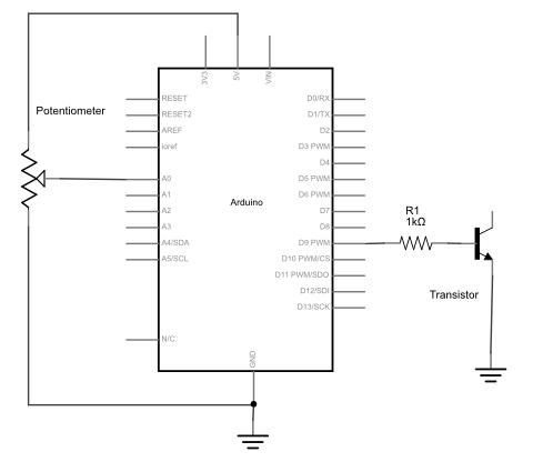
Figures 20 through 22 show how to connect the transistor’s input to the microcontroller’s output. Note that this circuit isn’t complete, because the transistor isn’t controlling anything yet.
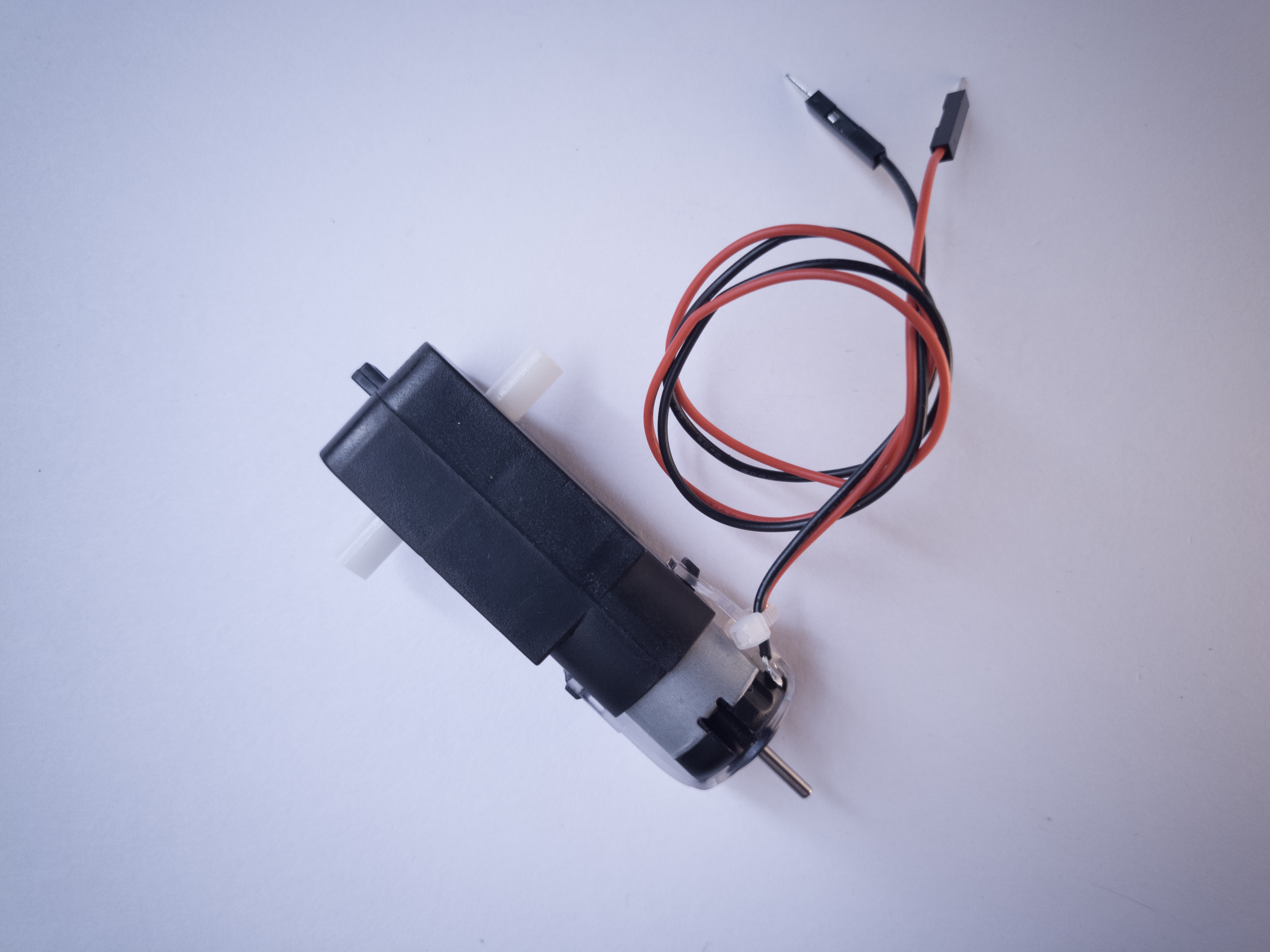
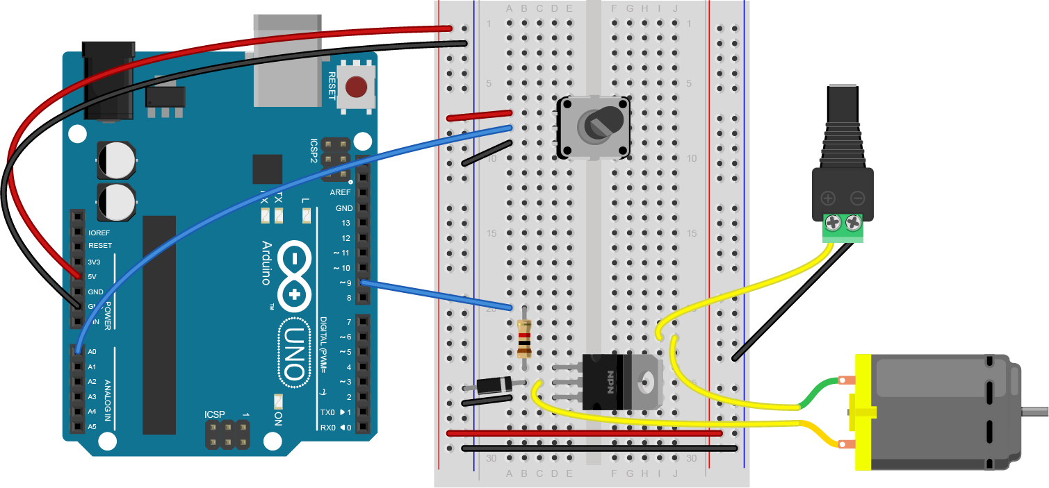
Connect a Motor and Power Supply
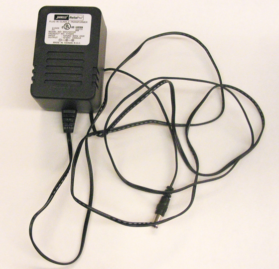
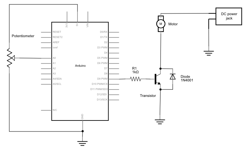
Attach a DC motor to the collector (or drain) of the transistor as shown in Figures 23 through 25. Most motors will require more current than the microcontroller can supply, so you will need to add a separate power supply as well. If your motor runs on around 9V, you could use a 9V battery. A 5V motor might run on 4 AA batteries (6V). You could also use a 12-volt DC wall adapter and a 5-volt regulator. A 12V battery may need a 12V DC wall adapter, or a 12V battery. The ground of the motor power supply should connect to the ground of the microcontroller on the breadboard.
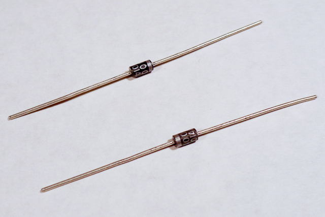
Add a 1N4001 power diode in parallel with the collector and emitter of the transistor, pointing away from ground. The diode protects the transistor from back voltage generated when the motor shuts off, or if the motor is turned in the reverse direction. Used this way, the diode is called a protection diode or a snubber diode. You can omit the diode if you don’t have one, as the transistors recommended here all have a built-in protection diode

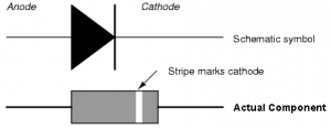
Be sure to add the diode to your circuit correctly. The silver band on the diode denotes the cathode which is the tip of the arrow in the schematic, like so in Figure 26:
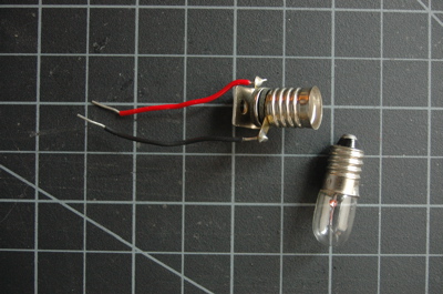
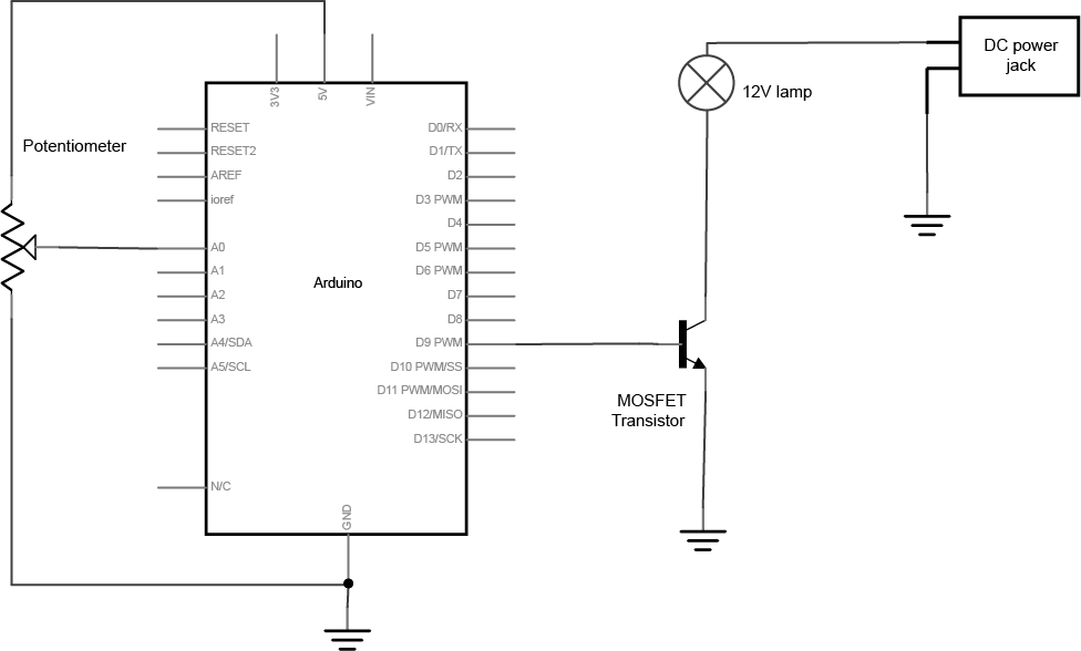
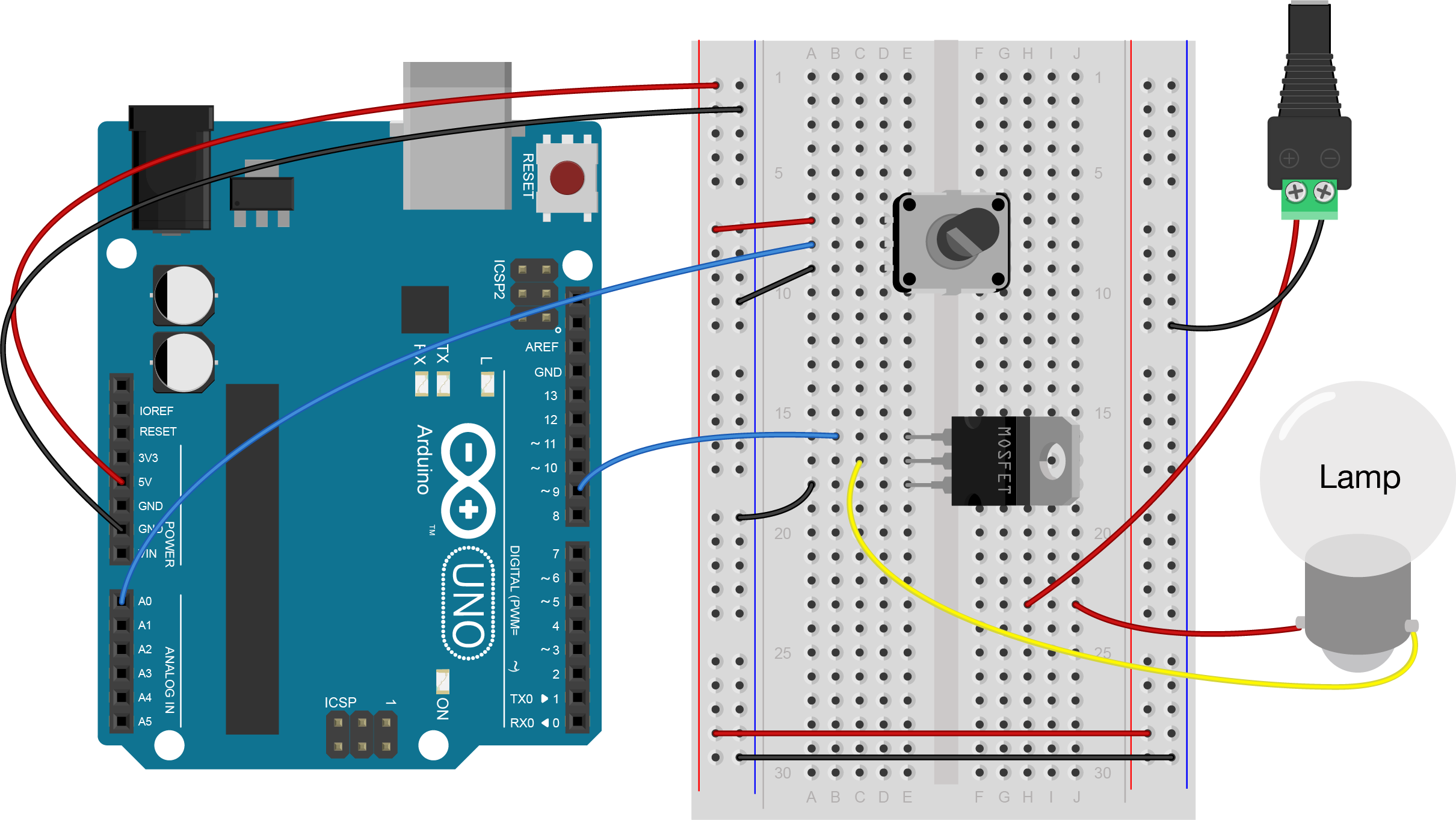
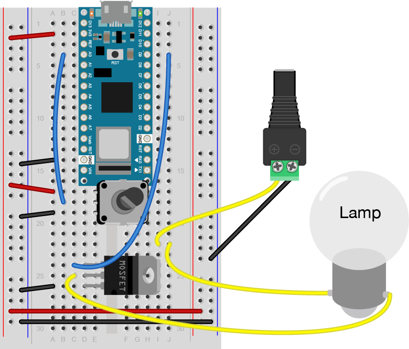
Connect a Lamp Instead of a Motor
You could also attach a lamp using a transistor. There are many 12V incandescent lamps, designed for use in track lighting, gallery lighting, and so forth. Nowadays, there are many 12V DC LED equivalents of the 12V AC lamps as well. Here are a few examples:
- Bi-Pin Socket for GU5.3/G4/GX5.3/GY6.35/GZ4 Base Bulbs – This socket works with the lamps below, and many others.
- GY6.35 LED Landscape Light Bulb – 40 Watt Equivalent – Bi-Pin LED Bulb – 450 Lumens
- GY6.35 LED Landscape Light Bulb – 40 Watt Equivalent – Bi-Pin LED Bulb – 275 Lumens
- MR16 LED Single Color Landscape Light Bulb – 30 Degree – 35W Equivalent
- 12V LED strip light, 19 in.
The lamp circuit in Figures 27 through 29 assumes a 12V lamp. MOSFETs are generally best for switching incandescent and LED lamps, so the circuit below uses a MOSFET. In the lamp circuit, the protection diode is not needed, since there’s no way for the polarity to get reversed in this circuit.
Program the microcontroller
Write a program to test the circuit, whether it’s a motor or a lamp. Your program should make the transistor pin an output in the setup method. Then in the loop, it should turn the motor on and off every second, just like the blink sketch does.
const int transistorPin = 9;    // connected to the base of the transistor

 void setup() {
   // set  the transistor pin as output:
   pinMode(transistorPin, OUTPUT);
 }

 void loop() {
   digitalWrite(transistorPin, HIGH);
   delay(1000);
   digitalWrite(transistorPin, LOW);
   delay(1000);
 }
Now that you see it working, try changing the speed of the motor or the intensity of the lamp using the potentiometer.
To do that, read the voltage of the potentiometer using analogRead(). Then map the result to a range from 0 to 255 and save it in a new variable. Use that variable to set the speed of the motor or the brightness of the lamp using analogWrite().
const int transistorPin = 9;    // connected to the base of the transistor

 void setup() {
   // set  the transistor pin as output:
   pinMode(transistorPin, OUTPUT);
 }

 void loop() {
   // read the potentiometer:
   int sensorValue = analogRead(A0);
   // map the sensor value to a range from 0 - 255:
   int outputValue = map(sensorValue, 0, 1023, 0, 255);
   // use that to control the transistor:
   analogWrite(transistorPin, outputValue);
 }
For the motor users: A motor controlled like this can only be turned in one direction. To be able to reverse the direction of the motor, an H-bridge circuit is required. For more on controlling DC motors with H-bridges, see the DC Motor Control lab.
Come Up with an Application
Now that you’ve got motor or lamp control, come up with an application.
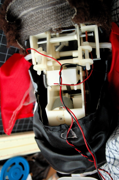
If you used a motor in this lab, consider any toys you have that have a motor you could take control over. Charley Chimp™ has a motor that’s easy to control from an Arduino, for example.
You could also consider simple movements in the work of artists like Jennifer Townley, Johannes Langenkamp (instagram), Nick Yulman, or Lu Lyu.
You’ve got the beginnings of a good desk lamp or table lamp, if you chose to use a light bulb in this lab. How will you control it? How will you mount the switchor the dimmer knob? You might also want to consider a gooseneck pipe to mount your socket on, and a socket that goes with it. Here are a few inspirations: